Component | Description |
|
|
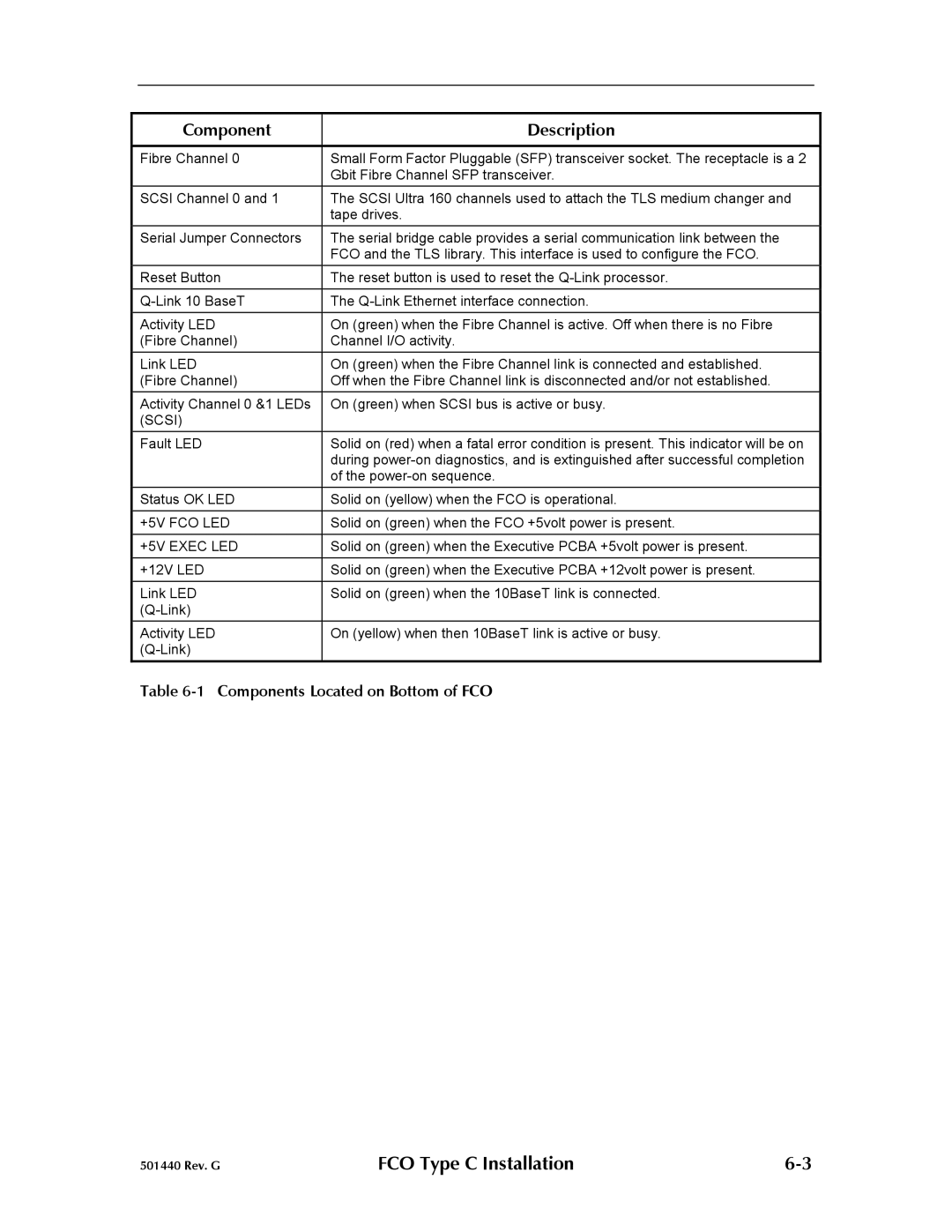
Fibre Channel 0 | Small Form Factor Pluggable (SFP) transceiver socket. The receptacle is a 2 |
| Gbit Fibre Channel SFP transceiver. |
SCSI Channel 0 and 1 | The SCSI Ultra 160 channels used to attach the TLS medium changer and |
| tape drives. |
Serial Jumper Connectors | The serial bridge cable provides a serial communication link between the |
| FCO and the TLS library. This interface is used to configure the FCO. |
Reset Button | The reset button is used to reset the |
The | |
Activity LED | On (green) when the Fibre Channel is active. Off when there is no Fibre |
(Fibre Channel) | Channel I/O activity. |
Link LED | On (green) when the Fibre Channel link is connected and established. |
(Fibre Channel) | Off when the Fibre Channel link is disconnected and/or not established. |
Activity Channel 0 &1 LEDs | On (green) when SCSI bus is active or busy. |
(SCSI) |
|
Fault LED | Solid on (red) when a fatal error condition is present. This indicator will be on |
| during |
| of the |
Status OK LED | Solid on (yellow) when the FCO is operational. |
+5V FCO LED | Solid on (green) when the FCO +5volt power is present. |
|
|
+5V EXEC LED | Solid on (green) when the Executive PCBA +5volt power is present. |
|
|
+12V LED | Solid on (green) when the Executive PCBA +12volt power is present. |
|
|
Link LED | Solid on (green) when the 10BaseT link is connected. |
| |
Activity LED | On (yellow) when then 10BaseT link is active or busy. |
|
Table 6-1 Components Located on Bottom of FCO
501440 Rev. G | FCO Type C Installation |