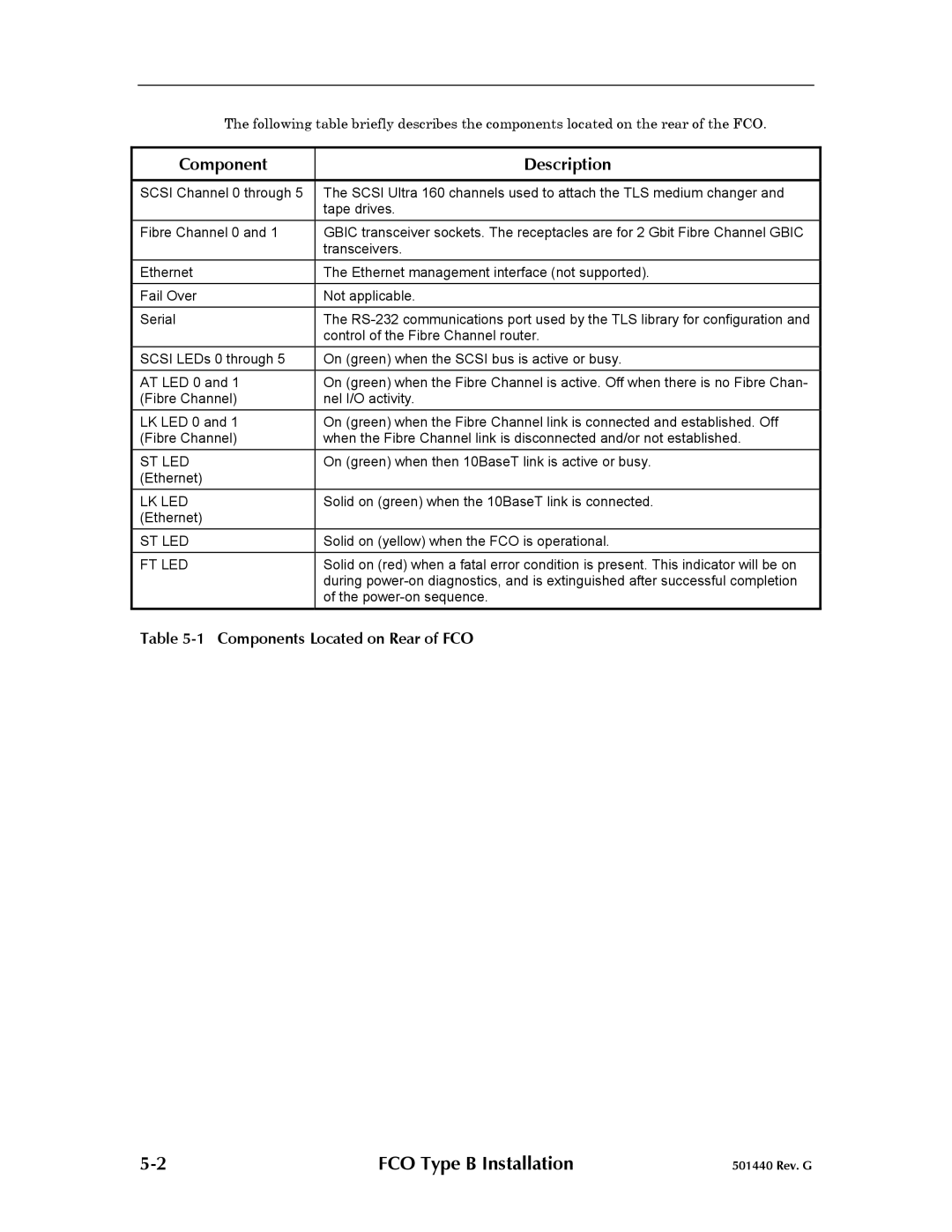
The following table briefly describes the components located on the rear of the FCO.
Component | Description |
|
|
SCSI Channel 0 through 5 | The SCSI Ultra 160 channels used to attach the TLS medium changer and |
| tape drives. |
Fibre Channel 0 and 1 | GBIC transceiver sockets. The receptacles are for 2 Gbit Fibre Channel GBIC |
| transceivers. |
Ethernet | The Ethernet management interface (not supported). |
|
|
Fail Over | Not applicable. |
|
|
Serial | The |
| control of the Fibre Channel router. |
SCSI LEDs 0 through 5 | On (green) when the SCSI bus is active or busy. |
|
|
AT LED 0 and 1 | On (green) when the Fibre Channel is active. Off when there is no Fibre Chan- |
(Fibre Channel) | nel I/O activity. |
LK LED 0 and 1 | On (green) when the Fibre Channel link is connected and established. Off |
(Fibre Channel) | when the Fibre Channel link is disconnected and/or not established. |
ST LED | On (green) when then 10BaseT link is active or busy. |
(Ethernet) |
|
LK LED | Solid on (green) when the 10BaseT link is connected. |
(Ethernet) |
|
ST LED | Solid on (yellow) when the FCO is operational. |
FT LED | Solid on (red) when a fatal error condition is present. This indicator will be on |
| during |
| of the |
Table
FCO Type B Installation | 501440 Rev. G |
