Fibre Channel 0 | Serial Jumper |
|
|
| Connectors |
| |
| SCSI Channel 1 |
| |
|
|
| |
|
|
|
|
|
| SCSI Channel 0 | Reset Button |
|
|
|
|
|
|
| |
|
|
|
|
|
|
|
|
|
|
|
|
|
| ACTIVITY CHANNEL 1 LED |
|
|
|
|
| (SCSI) |
|
|
|
LINK LED | +5V EXEC LED |
(Fibre Channel) |
|
FAULT LED | +5V FCO LED |
ACTIVITY CHANNEL 0 LED |
| LINK LED | |
+12V LED | |||
(SCSI) | |||
| |||
ACTIVITY LED | STATUS OK LED | ACTIVITY LED | |
(Fibre Channel) |
|
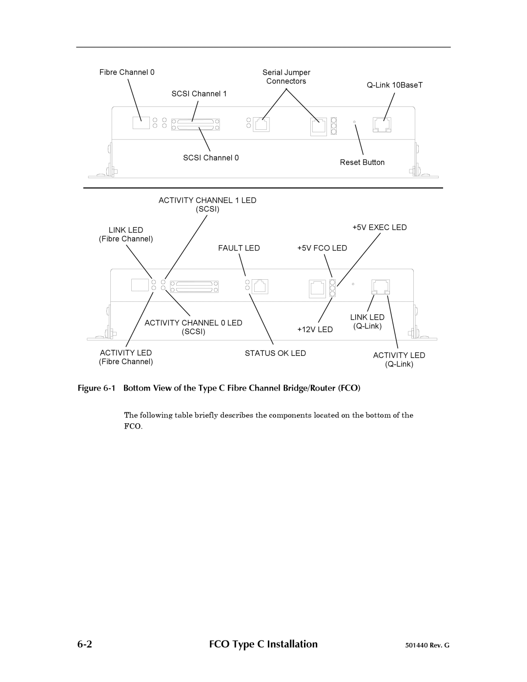
Figure 6-1 Bottom View of the Type C Fibre Channel Bridge/Router (FCO)
The following table briefly describes the components located on the bottom of the FCO.
FCO Type C Installation | 501440 Rev. G |
