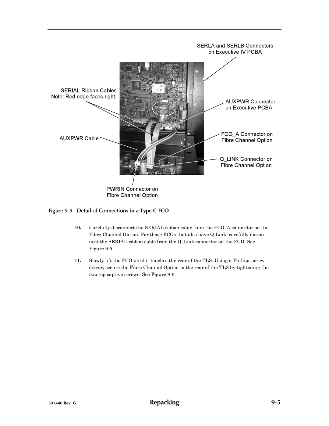
SERLA and SERLB Connectors
on Executive IV PCBA
SERIAL Ribbon Cables Note: Red edge faces right.
AUXPWR Connector on Executive PCBA
AUXPWR Cable | FCO_A Connector on |
Fibre Channel Option |
Q_LINK Connector on
Fibre Channel Option
PWRIN Connector on
Fibre Channel Option
Figure 9-5 Detail of Connections in a Type C FCO
10.Carefully disconnect the SERIAL ribbon cable from the FCO_A connector on the Fibre Channel Option. For those FCOs that also have
11.Slowly lift the FCO until it touches the rear of the TLS. Using a Phillips screw- driver, secure the Fibre Channel Option to the rear of the TLS by tightening the two top captive screws. See Figure
501440 Rev. G | Repacking |