| { |
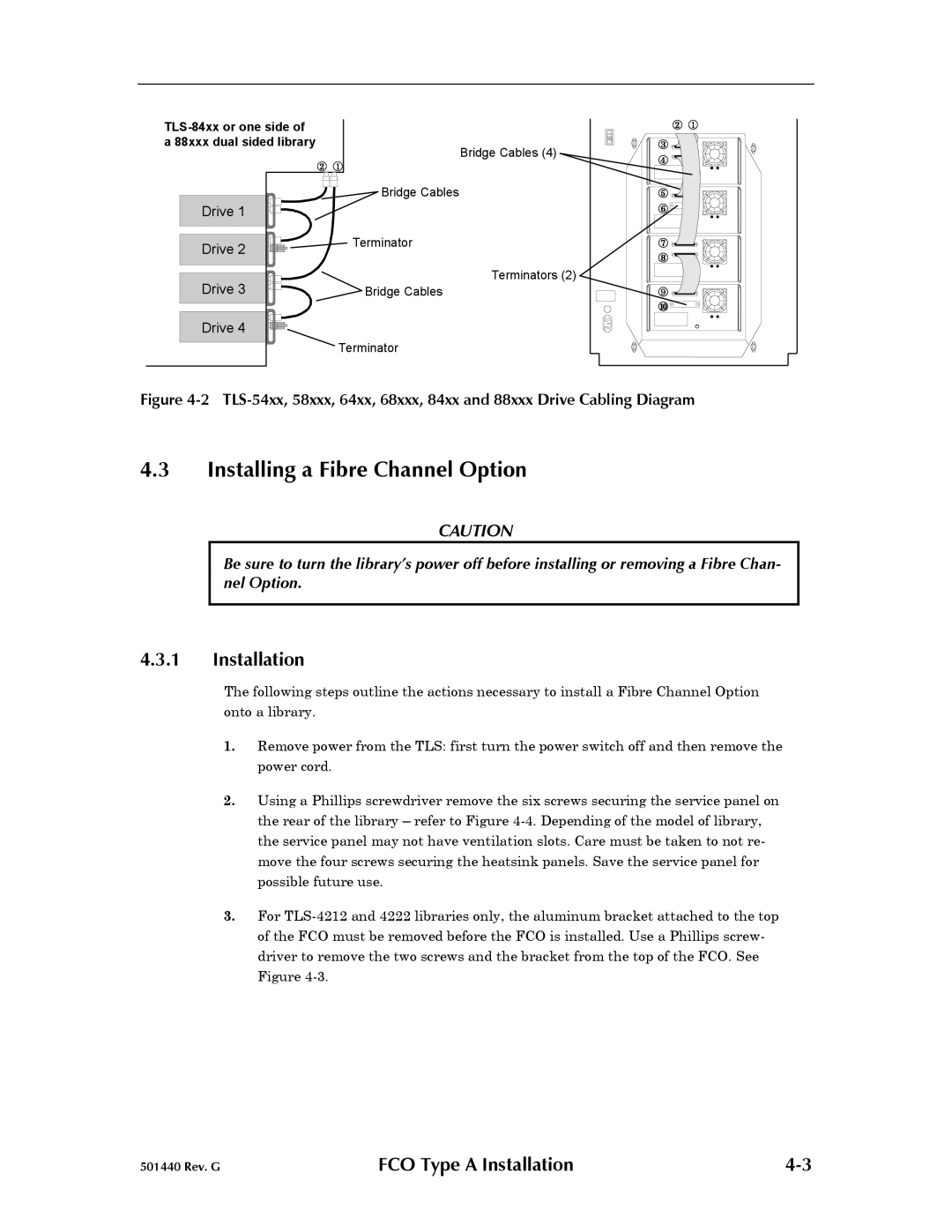
| Bridge Cables |
Drive 1 |
|
Drive 2 | Terminator |
| |
Drive 3 | Bridge Cables |
Drive 4 |
|
| Terminator |
Bridge Cables (4)
Terminators (2)
{
} ![]()
![]()
![]()
![]()
~ ![]()
![]()
![]()
![]()
![]()
![]()
![]()
![]()
![]()
![]()
![]()
![]()
![]()
![]()
![]()
![]()
![]()
![]()
![]()
![]()
![]()
![]()
|
|
Figure 4-2 TLS-54xx, 58xxx, 64xx, 68xxx, 84xx and 88xxx Drive Cabling Diagram
4.3Installing a Fibre Channel Option
CAUTION
Be sure to turn the library’s power off before installing or removing a Fibre Chan- nel Option.
4.3.1Installation
The following steps outline the actions necessary to install a Fibre Channel Option onto a library.
1.Remove power from the TLS: first turn the power switch off and then remove the power cord.
2.Using a Phillips screwdriver remove the six screws securing the service panel on the rear of the library – refer to Figure
3.For
501440 Rev. G | FCO Type A Installation |