SC-50d Series SC-60d Series
Page
RuncoCare Standard Features
RuncoCare Standard Two Year Limited Warranty
RuncoCare Claim Procedure
Extended Service Options
Copyright and Trademarks
Important Safety Instructions
Declaration of Conformity
Compliance Information
FCC Part
Page
Table of Contents
Install Anamorphic Lens Motor
External Control
Maintenance and Troubleshooting
Specifications
Operation
Xiv
List of Figures
List of Figures
About This Manual
Introduction
Degrade performance or cause a malfunction
Using This Manual
Certain features
Significance. They also provide supplemental information
Superwide format screen
Description, Features and Benefits
Optional Accessories
SC-50d/SC-60d at a Glance
Controls and Functions
SC-50d/SC-60d Input Panel
SC-50d/SC-60d Input Panel
Digital LED
RS232
Dual-Link DVI-I Input Slot
Analog LED
DHD Controller Front Panel
DHD Controller Front Panel
Panel
DHD Controller Rear
USB
Video 1 / Video 2 / Video
RS-232 To Accessory Box
Component / Scart 3 x RCA connectors
Display Control
DHD Controller SC-50d/SC-60d Remote Control Unit
SC-50d/SC-60d Remote Control Units
For more information about aspect ratios, refer to Table
Memory Preset Buttons
On / OFF
Cursor Buttons
Scart
HD 1 4 / HD 2
Comp Component
Hdmi 1 7 / Hdmi 2 8 / Hdmi 3 / Hdmi 4
Lenss Button
Zoom Button
Main Button
Remote Control
Installation
Installation specialist
Operation
Quick Setup
Installation Overview
Step Procedure For Details, Refer
Ambient Light
Installation Considerations
Projector Installation Options
Installation Type
SC-50d/SC-60d Lens Options and Throw Ratios Note
Position
Ceiling Installation
Floor Installation
Vertical and Horizontal
Horizontal Lens Shift Example only
Vertical and Horizontal Lens Shift Limits
Folded Optics
Input Timing Possible Audio Latency milliseconds
Synchronization Issues
Possible Audio Latency for Various Input Timings
Audio/Video
Ventilation Requirements for Enclosure Mounting
This can cause damage
Installing the Primary Projection Lens
Projector
Security Screws
Feet
Installing the Optional CineWide with AutoScope Lens Motor
Install Anamorphic Lens
Remove Projector Front
Mounting the SC-50d/SC-60d
Angle
Adjusting the Projection
Connections to the SC-50d/SC-60d and DHD Controller
Connecting the DHD Controller to the SC-50d/SC-60d
DHD
Hdmi Source Connections See Figure
Connecting Source Components to the DHD Controller
12. Component Video Source Connections
13. Rgbhv Source Connections
14. Scart Rgbs Source Connections
15. Composite Video Source Connections
Composite Source Connections See Figure
Audio Processor Secondary Display
Connecting an Audio
Processor or Secondary
Display Device to the DHD
17. RS-232 Control System Connection to DHD Controller
Additional Connections to the DHD Controller Optional
AutoScope Lens Motor
18. Connecting 12-volt Trigger Outputs
19. External IR Receiver Connection
20. Ethernet Network Connection to DHD Controller
Use only the AC power cord with the ferrite sleeve to
Primary Lens Adjustments Focus, Zoom and Position
Turning on the Power
Hold the Lens , Lens , Lens or Lens
You must enter a passcode to access the Service menu
Adjusting the Picture Orientation
21. Keystone and Pincushion Distortion
Adjusting the Image Geometry
Left Middle y setting also controls the Right Middle
You must enter a passcode to access the Calibration menu
It is extremely important that the primary lens is properly
Installing and Adjusting the CineWide Anamorphic Lens
As close to the primary lens as possible
Assembly to Lens Motor
Attach Lens Mounting
Carriage Plate
AutoScope
Configure Lens Motor
Adjust the Anamorphic
Trigger CineWide with
Too Low Correct position Too High
Geometry
Anamorphic Lens Top View
Alignment with
Working With
Lamp
Verify Proper Image
Operation
Using the On-Screen Menus
CUE
Service
Input Source
Main Menu
Aspect Ratio
Hdtv programs in their
Aspect Ratio Settings
Remote Aspect Ratio Control Description Key 169
Select 169 to view 169 DVDs
Native
Remote Aspect Ratio Control Description Key
Picture
Picture
Typical Gray Bar Pattern for Adjusting Contrast
Gray Yellow Cyan Green Magenta Red Blue
Gray Yellow Cyan Green Magenta Red Blue
Input Position
Resolution
Input Position
Overscan Modes
Adjust the Phase after adjusting Tracking see below
Memory Presets
Memory Presets
Sleep Timer
Sleep Timer
System
Signal
Information
Information
Calibration
Calibration ISF Settings
Control refer to RVR on
Color Temperature Presets and Associated Color Points
To Lamp on
RVR can only be used with the Power Lamp Mode setting refer
Copy/Paste
Copied settings are not retained after a power cycle
Test Patterns and Their Suggested Usage
Service
Should be used by ISF-certified technicians only
Input Names
Operation
If a Display Error, a device-specific
Operation
Firmware Upgrade functions
Operation
Onoff
DHD Controller does not transmit Hdmi CEC control
CEC setting
Regardless of the Standby LED setting
Regardless of the Logo LED setting
62 and ISF Day/Night Memory Presets
Operation
Lamp Replacement
Maintenance and Troubleshooting
Lamp Compartment Cover Retaining Screw
Re-attach the Left Exhaust Side Panel to the projector
Troubleshooting Chart
Troubleshooting Tips
Symptom Possible Causes Solution
Installing and Adjusting
Serial Communications
Port Configuration
Serial Command Syntax
External Control
Input Selection Commands
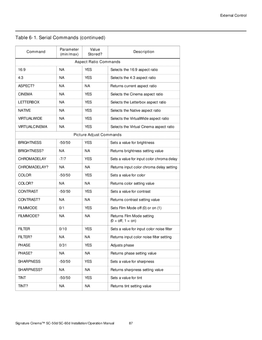
Serial Commands
Picture Adjust Commands
Output Shift Commands
Input Position Commands
Enter key
Miscellaneous Commands
Exit key
Command Parameter Value Description Min/max
Using Discrete IR Codes
With Toggle Bit = Hex Binary Function Start
Command Bits
RC5 Control Codes for the DHD Controller
Remote Control With Toggle Description Button Name Bit =
RC5 Data
ST60MIN
CEC Commands Supported by the DHD Controller
Using Hdmi CEC Messages
Opcode Value Supported? √ = Yes, = No Initiator Follower
Messages from the Hdmi Audio Out connector
External Control
SC-50d/SC-60d Projector Specifications
Specifications
SC-50d/SC-60d Projector Specifications
Specifications are subject to change without notice
DHD Controller Specifications
DHD Controller Specifications
CTUVus, FCC class B, CE, RoHS, China RoHS, Weee
SC-50d/SC-60d
Dimensions
CineWide with AutoScope Assembly
SC-50d/SC-60d Dimensions with
Composite 1 Composite 2 Composite
Supported Signal Timings by Input
Supported Timings
Component
Rgbs
Format Resolution Frequency Rate Hz MHz KHz
105
PAL-M
Page
020-1105-00 Rev. a March