Operation
Use the Calibration menu to perform advanced picture quality adjustments. This menu should be used by
You must enter a passcode to access the Calibration menu.
Note
To recall the ISF Night or ISF Day settings, select “ISF Night” or “ISF Day” from the Memory Presets menu (see page 62) or use the corresponding remote control buttons.
Display Color: Use the Display Color settings to adjust the color balance at the DHD Controller output. These settings are saved independently for each input and display mode.
•Gain: Use the Gain controls to correct color imbalances in the bright areas of the image. A good way to do this is to use a test pattern consisting mostly of solid white areas, such as an 80 IRE “window” pattern. If the white areas contain traces of red (Pr), green (Y) or blue (Pr), decrease the Gain for that color.
•Offset: Use the Offset controls to correct color imbalances in the dark areas of the image. A good way to do this is to use a test pattern consisting mostly of dark gray areas, such as a 30 IRE “window” pattern. If the gray areas contain traces of red (Pr), green (Y) or blue (Pr), decrease the Offset for that color.
•Gamma: Select Gamma from the Display Color menu to choose a
•Mode: With the
•Simple: Use the Simple Gamma control to perform gamma correction at the display according to a simple power law gamma function. The value chosen here corresponds to the power variable in this equation:
Output = InputPower
The DHD Controller applies this gamma curve to all three primary color channels (red, green and blue).
•Advanced: To select a custom gamma curve, select Mode from the Gamma menu and set it to Advanced. Then, select Advanced from the Gamma menu to select one of up to 20
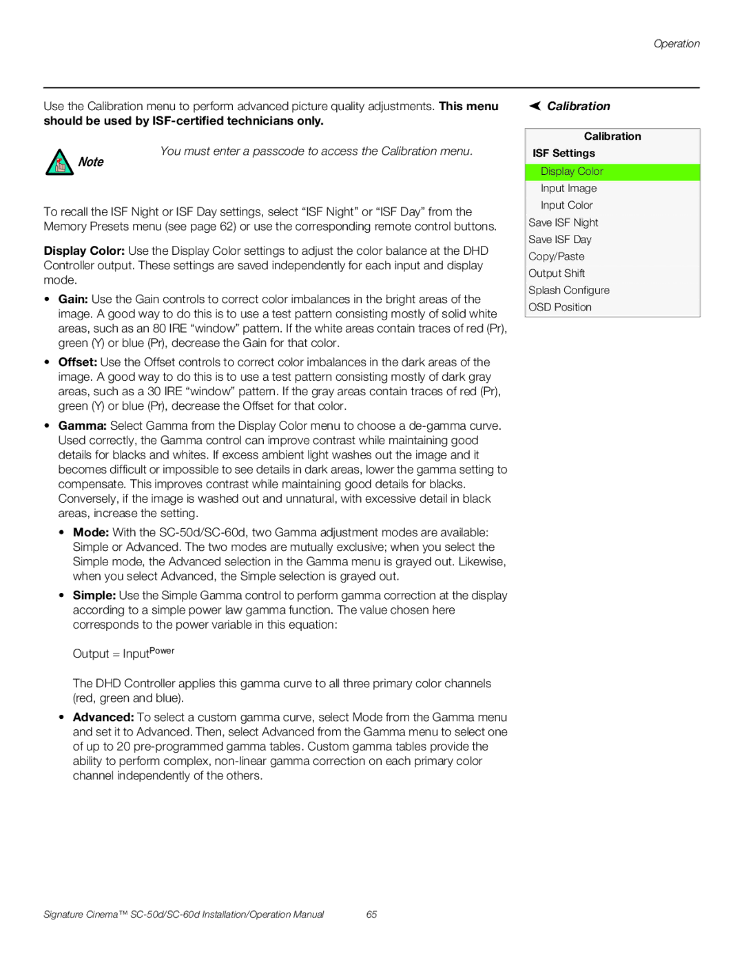
 Calibration
Calibration
ISF Settings
Display Color
Input Image
Input Color
Save ISF Night
Save ISF Day
Copy/Paste
Output Shift
Splash Configure
OSD Position
Signature Cinema™ | 65 |