Contents
Propos de ce manuel
About this manual
Features
Contents
For the customers in Canada
Information to User
Pour la clientèle canadienne
Precautions
Video output connector Video OUT BNC type
Power indicator Power
Alarm output terminal ALARM, C, a
Parts Names
Lens iris output connector Lens
Camera setup section under the cover
Menu setting button SET
Cursor button Cursor
Lens mount cap
Concerning AUTO-IRIS Lenses
If using a Video type auto-iris lens
DC type auto-iris lens
Video type auto-iris lens
Remove the lens mount cap from the camera
Mounting the Lens
Mount type lens
Flange-back adjustment
Rewiring the lens cable in the lens iris plug
Basic connection for monitoring or recording
Connections
Coaxial cable type and maximum length
Connection to a VCR
RS-485 terminal connections
Connection to a multiplexer
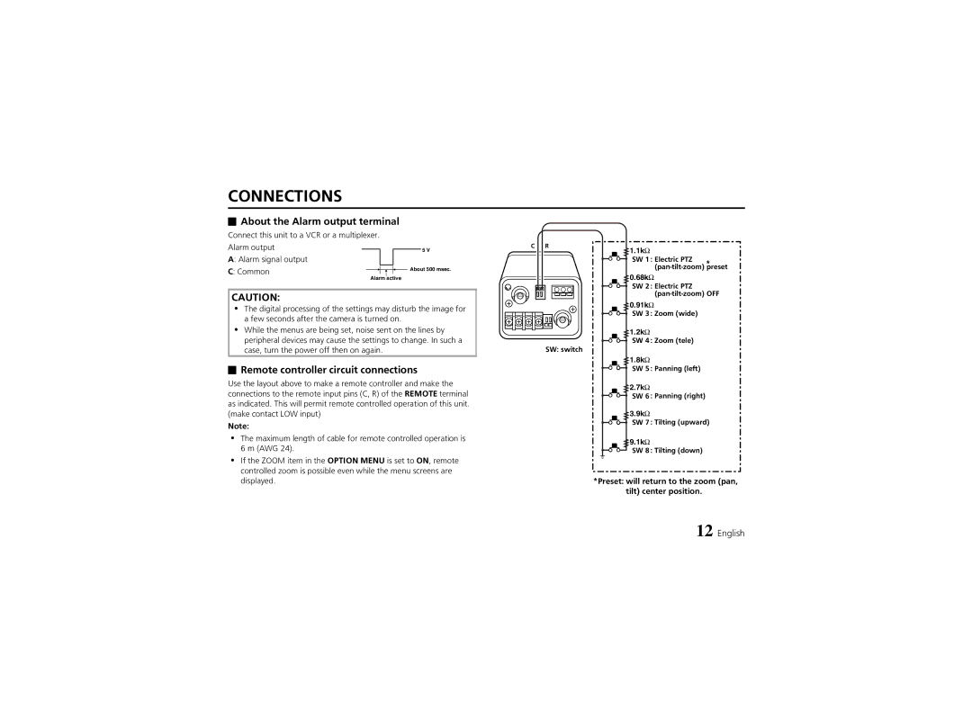
Remote controller circuit connections
About the Alarm output terminal
Preset will return to the zoom pan, tilt center position
Using the Cursor button
Using the Menu Screen
Switching to sub-menu screens
Switching to the Main Menu screen
Using the Menu Screen
Then press the SET button
Language setting
Example To set the camera ID to BN1
Camera ID setting
Determining the start position for character input
Changing the camera ID to a new ID
Display will return to the Camera ID Setting screen
Internal synchronization INT
Sync settings
External sync VBS
Power supply synchronization setting L L
External sync setting VBS
Menu Back END
AI Auto Iris mode setting
Iris setting
Lens Type setting
BLC setting
Adjust the Iris Level setting DC type lens only
AI/BLCMULTI
BLC Window Weighting screen will be displayed
BLC/EVAL 5-section photometry mode setting
Returning the values to the default settings
Weighting
EI Electronic Iris mode setting
Sense UP setting
Press the Cursor l, then d or c button until EI
Automatic color temperature tracking setting ATW
White Balance setting
Manual white balance MWB
White BALANCE/ATWMASKING
Masking setting
Menu Back END
Press and hold the SET button
Push-lock white balance adjustment AWC
Manual white balance setting MWB
Short mode Short
Electronic Shutter setting
Long exposure mode Long
For Short mode
When Motion is set to ON, Long mode cannot be selected
For Long mode
Iris Sense UP mode has been set. Refer to
Motion setting
Example
Mask area setting function Masking
Size setting function Size
Sensitivity setting function Sensitivity
Alarm interval setting function Interval
Üü, íí, óó, ññ
Direction setting
V vertical value is flashing, then press the Cursor c button
Size setting
Motion Size display table Returning to the default setting
MOTION/MASKING
Menu Back END
This sets the movement amplitude of subjects on the screen
Sensitivity setting
Maximum
MOTION/ZOOM, Interval
Zoom setting
Alarm Sign setting
Interval setting
Camera ID flashes on-screen when a movement is detected
Image is zoomed in when a movement is detected
Checking the detected movements set by the Motion item
Active
Move Differ
Option settings
Aperture setting
Gamma setting
AGC setting
Panning
For FIX mode
OPTION/FIXI Tilt
Returning to the default settings
Zooming
For VAR mode
OPTION/VAR ZOOM, Tilt
RS-485 setting
Mirror setting
Terminate setting
Address setting
About SW No
SET button
Initial setting
Operations using the camera Menu screens
Operations Using the System Controller
Electronic zoom
Operations using the camera command Camera button
Iris level operations
Backlight correction settings
Setting the Sense UP and electronic shutter
White balance and AWC-LOCK settings
4321
Menu Display
Menu Display
No picture on the monitor screen
Troubleshooting
Picture is not clear
Camera
Specifications
Dimensions mm
Accessories
Exclusions

 About the Alarm output terminal
 Remote controller circuit connections