Sanyo Commercial Solutions
R410A Models Indoor Units
Outdoor Units
Optional Controllers
For safe installation and trouble-free operation, you must
…In a Room
…In Moist or Uneven Locations
…In an Area with High Winds
Amount 353 oz Amount 529 oz
Countermeasures
Care regarding tubing
Be sure to recharge the refrigerant only in liquid form
Different tools required
Manifold gauge Vacuum pump
Compressor specifications are different
Single-outlet valve
Existing tubing cannot be used especially R22
Refrigerating machine oil differs R22
Contents
Electrical Wiring 5-1. General Precautions on Wiring
HOW to Process Tubing
AIR Purging
Test RUN 8-1. Preparing for Test Run
Tools Required for Installation not supplied
Accessories Supplied
Outdoor Unit Part name
Type of Copper Tube and Insulation Material
For sealing recessed portion of power supply
4-Way Air Discharge Semi-Concealed X-Type
1-Way Air Discharge Semi-Concealed
Concealed Duct
Concealed Duct High-Static Pressure
Ceiling-Mounted
Wall-Mounted
4-Way Air Discharge Semi-Concealed XM Type
Tubing Length
H3 C
Tubing Size 10 Main Tubing Size LA
11 Main Tubing Size After Distribution LB, LC
12 Outdoor Unit Tubing Connection Size a D
BTU/h 95.500 153.600
15 Refrigerant tubing Existing tubing can be used
17 Refrigerant Charge Amount at Shipment for outdoor unit
System Limitations 18 System Limitations
Common solenoid valve kit
Header joint system
Tube branching methods horizontal use
Header joint system Indoor
Tubing size with thermal insulation
Model name Cooling capacity after distribution Remarks
Suction Tube
Size Part B Part C Part D Part E Part F Part G Part H Inch
21 Dimensions for connections of each part
Discharge Tube Liquid Tube
Precautions on Installation of Solenoid Valve Kit
Types and specifications
Specifications
Optional Solenoid Valve Kit
Unit
Installation of Solenoid Valve Kit
Relay kit Front
R410A additional charging absolutely must
Be done through liquid charging
Example Use the same tools for R22 and for R410A
Main tubing Distribution joint tubing
Main tubing
Remark
Ceiling-MountedType
Wall-Mounted Type
Indoor Unit
Front view
Outdoor Unit
Precautions When Installing in Heavy Snow Areas
Without snow- proof ducting Without platform
Unit installation
Ceiling panel
Unit Ceiling panel
Air direction Front direction
Air direction
Suspending the Indoor Unit
Placing the Unit Inside the Ceiling
Installing the Drain Piping
Start when you short the pin
Be careful since the fan will
On the indoor control board
Removing the corner cover
Installing the Ceiling Panel
Wiring the Ceiling Panel
Attaching the air-intake grille
Checking After Installation
When Removing the Ceiling Panel for Servicing
Adjusting the Auto Flap
Special Remarks DC Fan Tap Change Procedure
Suspending the Indoor Unit
Placing the Unit Inside the Ceiling
Installing the Drain Piping
Do not install an air bleeder as
This may cause water to spray
From the drain pipe outlet
How to Install the Ceiling Panel Main unit
Before Installing the Ceiling Panel
Checking the Drainage
Checking the unit position
Installing the Ceiling Panel
Wiring the Ceiling Panel
How to Attach the Corner & Air-Intake Grille
Checking After Installation
When Removing the Ceiling Panel for Servicing
Adjusting the Auto Flap
22-3/64
23-5/8
Confirm that the unit is
Level. If it is not level, water
Leakage may occur
Be sure to use a level gauge
Installing the Drain Piping
3WAYECO-iUS.indd 2008/02/07
Electrical Power Wiring Wiring connections
Wiring
M5 ss40
Ss12 or 5/32 ss15/32 For fastening
Removing the intake grille
Removing the side panel
Air leakage
Installing the side panel and intake grille
Installing the intake grille
Others Check after installation
If a wireless remote controller is used
Inspection access
27/32 Indoor unit
Air outlet duct flange
Refrigerant tubing
Enough to support the weight of the unit
It is important that you use extreme care
Supporting the indoor unit inside
Ceiling. Ensure that the ceiling is strong
Section directly after the connection port can be raised a
Maximum of 19-11/16. Do not raise it any higher than
19-11/16, as this could result in water leaks. Fig
How to read the diagram
Be careful since the fan will start when you
Short the pin on the indoor control board
Increasing the Fan Speed
23-5/8 for checking and servicing the electrical system
17-23/32
31/32
Indoor Fan Performance How to Read the Diagram
Min -31/32 Inspection plug
Refrigerant tubing drain hose position
Wall and ceiling side opening position
It is important that you use
Extreme care in supporting
Indoor unit from the ceil
Fixture Double nut Field supply
Approx 63/64 Ceiling Surface Washer Nut
Duct for Fresh Air
Shaping the Tubing
Rear cover
Downward gradient Min /100
How to carry out power supply wiring
Check local electrical codes
Regulations before wir
Ing. Also, check any specified
Installing the Rear Panel onto the Wall
Selecting and Making a Hole
If the Wall is Wooden
Removing the Grille to Install the Indoor Unit
If the Wall is Brick, Concrete or Similar
Removing the grille
Attaching the grille
Installing the Drain Hose
Do not supply power to the unit or operate
Shaping the Tubing Right-rear tubing
Left or left-rear tubing
KHX0752 / 0952 / 1252
KHX2452
Installing the Outdoor Unit
Positions where anchor bolts are fastened
Transporting
Remove the Brackets Used for Transport
Routing the Tubing
Prepare the Tubing
Connect the Tubing
Refrigerant tube port
Tubing size mm Outer dia Thickness
Tightening torque for each cap
Work method
General Precautions on Wiring
Outdoor unit Time delay fuse or Circuit capacity
Inter-outdoor unit control wiring
Use shielded wiring
Wiring System Diagram
Power
Wiring Controller
For K, A, X, T, U and D Types
For XM Type
XM Type
Outdoor unit Indoor unit
How to connect wiring to the terminal For stranded wiring
Important Note When Wiring for Common Type
Type
Type
Important Note When Wiring for XM Type
XM Type
Connecting the Refrigerant Tubing
Flaring Procedure with a Flare Tool
Use of the Flaring Method
Deburring
Tube diameter Tightening torque
Approximate
Two tubes arranged together
Three tubes arranged together
Four tubes arranged together
Finishing the Installation
Taping the Tubes
Air Purging with a Vacuum Pump for Test Run Preparation
Leak test
Manifold gauge Vacuum pump
Evacuation
45 min. or more 90 min. or more
Charging additional refrigerant
Use a cylinder designed for use with R410A
Finishing the job
Test RUN
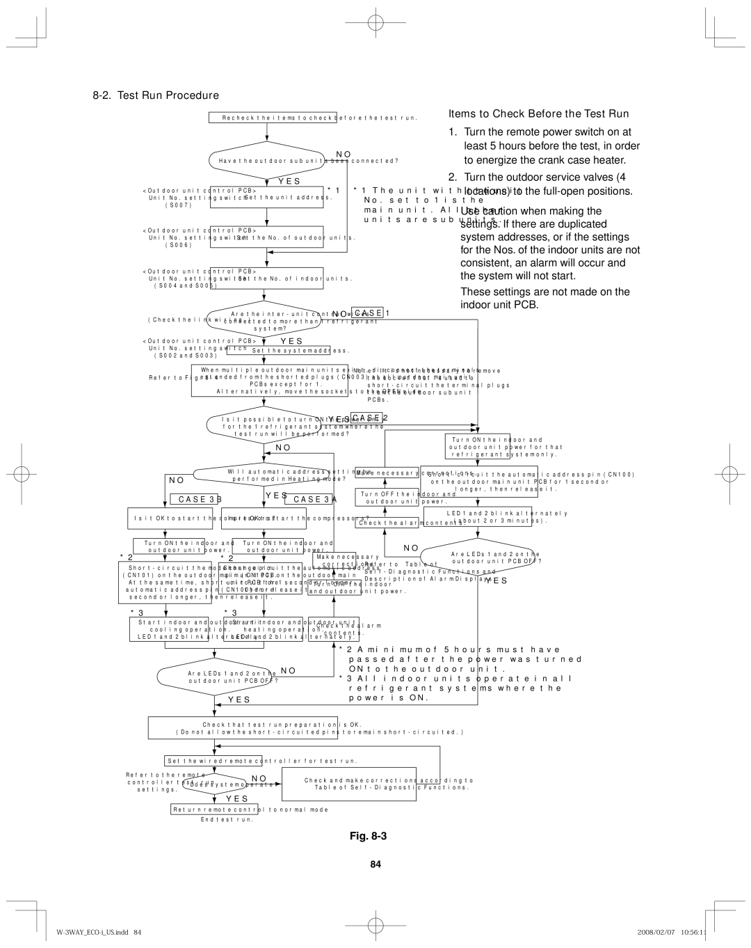
Test Run Procedure
Items to Check Before the Test Run
Unit with the unit
Indoor unit setting S004 Rotary switch, red
Address setting of main outdoor unit S007 Unit No. setting
Main Outdoor Unit PCB Setting
Auto Address Setting Basic wiring diagram Example
Automatic Address Setting from the Outdoor Unit
No main unit Settings
Outdoor main/sub
22-9
Automatic Address Setting no compressor operation
Automatic Address Setting from Outdoor Unit
3 OFF
Automatic Address Setting in Heating Mode
Automatic Address Setting in Cooling Mode
Automatic Address Setting* from the Remote Controller
Display during automatic address setting
LED 2
Blink alternately
If 1 indoor unit is connected to 1 remote controller
Remote Controller Test Run Settings
Checking the indoor unit addresses
Possible cause of malfunction
LED
Message
Alarm messages displayed on system controller
Way Air Discharge Semi-Concealed Type X, XM Types
Should the power fail while the unit is running
Tips for Energy Saving
Soot
Type 1-WAY
Way air discharge semi-concealed type a
Troubleshooting
100
Concealed Duct High-Static Pressure Type U, D Types
Type standard static pressure
Type high static pressure
101
On the wired remote control unit
102
CEILING-MOUNTED
103
Or soot
104
105
Tips for Energy Saving
106