Sun Microsystems, Inc
Page
Contents
Page
Replacing Cold-Swappable Components
Safety Information
Replacing Hot-Swappable and Hot-Pluggable Components
Page
XVR-50 Graphics Accelerator
Specifications
Index Index-1
Checking Device Configuration D-5
HD15 Video Output Port D-6
Preface
Using Unix Commands
Shell Prompts
Accessing Sun Documentation
Typographic Conventions
Module
Sun Blade T6320 Server Module Safety and Compliance Manual
Sun Welcomes Your Comments
Third-Party Web Sites
Documentation, Support, and Training
Component Overview
Sun Blade T6320 Server Module Product Description
1Sun Blade T6320 Server Module With Chassis
Front View
3Cable Dongle Connectors
Insert the connector straight into the server module
Connections
1Sun Blade T6320 Server Module Features
During normal system operation
SAS/SATA
2Interfaces With the chassis
4Field-Replaceable Units
3Sun Blade T6320 Server Module FRU List
Hard Drive on
Sun Blade T6320 Server Module FRU List
Multicore Processor Information
Support for RAID Storage Configurations
Sun Blade RAID 0/1 G2 Expansion Module
Finding the Serial Number
MAC address
Alom CMT example
Additional Service Related Information
Sun Blade T6320 Server Module Diagnostics
Alom CMT CLI
Sun Blade T6320 Server Module Diagnostics Overview
Sun Blade T6320 Server Module Diagnostics
1Diagnostic Flowchart
System LEDs on
1Diagnostic Flowchart Actions
FRU-namedeemed faulty and disabled
FB-DIMM Configuration Guidelines
Memory Configuration and Fault Handling
Supported FB-DIMMs and Part Numbers
Dimm Installation Rules
BR1/CH0/D0 BR0/CH0/D0 BR2/CH0/D0 BR3/CH0/D0
3FB-DIMM Installation Rules
You can also use -2to identify the DIMMs you want to remove
FB-DIMM Configuration and Installation
2FB-DIMM Configuration and Installation
Memory Fault Handling
Troubleshooting Memory Faults
Front Panel LEDs and Buttons
Interpreting System LEDs
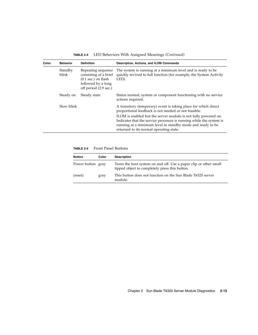
3LED Behavior and Meaning
LEDs have assigned meanings, described in Table
4LED Behaviors With Assigned Meanings
5Front Panel Buttons
Ethernet Port LEDs
Using Ilom for Diagnosis and Repair Verification
Ilom
Fru at location is OK
Using the Ilom Web Interface For Diagnostics
8ILOM Login Screen
Changing Post Settings With the Ilom Web Interface
Page
Type the show command to see the current Post settings
Changing Post Settings With the Ilom CLI
Displaying System Faults
10Fault Management Page Example
Viewing Fault Status Using the Ilom Web Interface
11Faulted Component ID Window
Viewing Fault Status Using the Ilom CLI
Show /SYS/MB/VVCORE
Displaying the Environmental Status with
Sun Blade T6320 Server Module Diagnostics
Displaying FRU Information
Using the Ilom Web Interface to Display FRU Information
15Static FRU Information in the Ilom Web Interface
Using the CLI to Display FRU Information
Show /SYS/MB
At the -prompt, type the show command
Segment TH
Controlling How Post Runs
Running Post
16. This parameter overrides all other
6Parameters Used For Post Configuration
16Flowchart of Ilom Variables for Post Configuration
7describes how the Post settings will execute
Using the Web Interface to Change Post Parameters
7POST Modes and Parameter Settings
Changing Post Parameters
17Setting Post Parameters With the Ilom Web Interface
18Changing Power Settings with the Ilom Web Interface
Show /HOST/diag
Using the CLI to Change Post Parameters
Type the set command to change the Post parameters
Post error messages use the following syntax
Power cycle the server module to run Post
Interpreting Post Messages
Interpret the Post messages
Clearing Post Detected Faults
19Enabling Components With the Ilom Web Interface
Clearing Faults With the Web Interface
Reboot the server module
Clearing Faults With the Ilom CLI
Set componentstate=enabled
Cd /SYS/MB/CMP0/P32
Clearing Hard Drive Faults
Using the Solaris Predictive Self-Healing Feature
Clearing Faults Manually with Ilom
# fmdadm faulty
Using the fmadm faulty Command
# fmdump
Using the fmdump Command
Follow the suggested actions to repair the fault
Clearing PSH Detected Faults
After replacing a faulty FRU, boot the system
Clearing the PSH Fault From the Ilom Logs
Clear the fault from all persistent fault records
# fmadm faulty
Set /SYS/component clearfaultaction=true
Collecting Information From Solaris OS Files and Commands
Checking the Message Buffer
Log in as superuser
Type the syslogd command
Managing Components With Automatic System Recovery Commands
Log in as superuser Type the following command
If you want to view all logged messages, type this command
SYS/component
8ASR Commands
An example with no disabled components
Displaying System Components With the show /SYS Command
An example showing a disabled component
Show /SYS/MB/USB0
9Sample of installed SunVTS Packages
Checking SunVTS Software Installation
Exercising the System With SunVTS
# pkginfo grep -i vts
Enable the remote display. On the display system, type
Exercising the System Using SunVTS Software
Where test-systemis the name of the server you plan to test
Steps for Exercising the System With SunVTS Software
20 SunVTS BI
# /opt/SUNWvts/bin/sunvts -display display-system0
Optional Select the test category you want to run
Start testing
Optional Customize individual tests
10Useful SunVTS Tests to Run on This Server
To Reset the Root Password to the Factory Default
Resetting the Password to the Factory Default
Change the root password
Remove the server module from the modular system chassis
Sun Blade T6320 Server Module Diagnostics
Page
Hot-Plugging a Hard Drive
Hot-Pluggable Hard Drives
Removing a Hard Drive
Rules for Hot-Plugging
HDD2 HDD0 HDD1 HDD3
2Hard Drive Locations, Release Button, and Latch
Replacing a Hard Drive or Installing a New Hard Drive
Adding PCI ExpressModules
Page
Replacing Cold-Swappable Components
Safety Information
Using an Antistatic Wrist Strap
Safety Symbols
Electrostatic Discharge Safety
Using an Antistatic Mat
Common Procedures for Parts Replacement
Required Tools
Shutting Down the System
Log in as superuser or equivalent
Using the Ilom Web Interface to Shut Down the Server Module
Notify affected users
Save any open files and quit all running programs
1Powering Off the Server Module with the Ilom Web Interface
Using the Ilom CLI to Shut Down the Server Module
Set /SYS/LOCATE value=fastblink
At the Ilom -prompt, type the set /SYS/PS0
Set /SYS/ preparetoremoveaction=true
2Disconnecting the Cable Dongle
3Removing the Sun Blade T6320 Server Module From the Chassis
Open the ejector levers Figure
4Stack Five Server Modules or Fewer
Removing the DIMMs
This section describes how to remove and replace DIMMs
Removing and Replacing DIMMs
6DIMM Locate Button and Dimm LEDs
Locate the DIMMs that you want to replace Figure
Sixteen DIMMs installed
FB-DIMM Configuration
8Removing DIMMs
Replacing the DIMMs
Verifying Dimm Installation
Removing and Replacing the Service Processor
Removing the Service Processor
9Removing the Service Processor
Prom is keyed to ensure proper orientation
Replacing the Service Processor
Removing and Replacing the Battery on the Service Processor
11Removing the Battery From the Service Processor
Replacing the Battery on the Service Processor
Set /SP/clock datetime=10
Removing the RAID 5 Expansion Module
12Removing the RAID Expansion Module
Installing the RAID 5 Expansion Module
13Replacing the RAID 5 Expansion Module
Verifying the RAID 5 Expansion Module Installation
Ok show-disks
Return to the root node by using the unselect-devcommand
Configuring the RAID 5 Expansion Module
For details, see Appendix B and Appendix C
Ok .properties
Additional Information
Creating a Bootable Array With the RAID 5 Expansion Module
Removing the RAID 0/1 Expansion Module
For more information, refer to the following documents at
14Removing the RAID Expansion Module
Replacing the RAID 0/1 Expansion Module
15Replacing the RAID 0/1 Expansion Module
Verifying the RAID 0/1 Expansion Module Installation
Replacing the Cover
Finishing Component Replacement
Reinstalling the Server Module in the Chassis
17Inserting the Server Module in the Chassis
Page
Lbs fully configured
Physical Specifications
Table A-1Exterior Dimensions
77 kg
Operating Temperature and Altitude
System Environmental Specifications
Non-Operating Temperature and Altitude
Temperature -40˚ C to 60˚ C Maximum altitude 40,000 ft
Figure A-2Motherboard Block Diagram
Motherboard Block Diagram
Page
P E N D I X B
Install and connect the HBA and disk drives
About Creating a Bootable Array on a Sparc System
Creating a Bootable Array Task Map
Modify two locations on the network install server
Modifying the Miniroot Directory On the Install Server
# cd /cdrom/raidlive/s0/Raidcard
To Modify the Miniroot Directory
# cp -r SUNWaac installdirpath/Solaris10/Product
To Modify the Product Installation Directory
Ok boot net -s
Building a Logical Drive On Which to Install the Solaris OS
To Create a Logical Drive Using a Network Install Server
# ./arcconf Create 1 Logicaldrive MAX 5 0 2 0 3 0
# cd /opt/StorMan # ./arcconf Getconfig
Ok boot cdrom
To Create a Logical Drive Without a Network Install Server
Bringing the drive online
Sc shownetwork
To Delete a Logical Drive on the REM
Run the Create command as shown in the following example
To Label the Newly Created Logical Drive
# ./arcconf Getconfig 1 LD
# ./arcconf Delete 1 Logicaldrive
# devfsadm
# init
Next Steps
# format
Additional Information
Complete the procedures in Appendix B
Preparing to Install the Solaris OS
To Prepare to Install the Solaris OS
This section contains the following subsection
Use the df command to verify the following
# cd /cdrom/Solaris10/Product # pkgadd -R /a -d. SUNWaac
# reboot
Apply the HBA driver package, SUNWaac
Next Steps
XVR-50 Graphics Accelerator
Features
Table D-1XVR-50 Graphics Accelerator HD15 Video Formats
Video Formats
Table D-1lists video formats supported by the HD15 port
This example shows a list of graphics devices displayed
Sun OpenGL for Solaris Software
Man Pages
Optional Video Output
Default Color Depth
Log out and then log back in for the change to take effect
Checking Device Configuration
HD15 Video Output Port
Host% fbconfig -dev pfb0 -prconf
Index
FRU
Man page, D-3, D-4
Post
SYS/MB server module FRU name
Index-5