VISION 5000 Videoconferencing System | Appendix 4 |
Appendix 4: LED indication
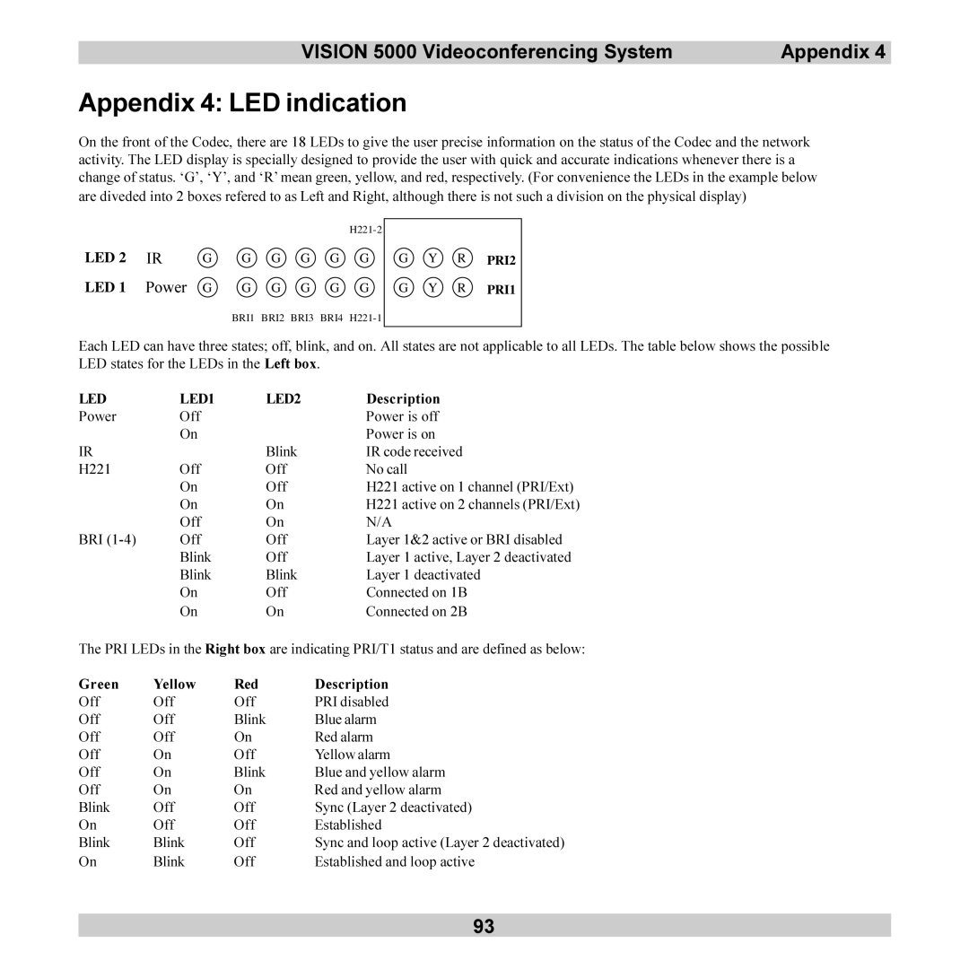
On the front of the Codec, there are 18 LEDs to give the user precise information on the status of the Codec and the network activity. The LED display is specially designed to provide the user with quick and accurate indications whenever there is a change of status. ‘G’, ‘Y’, and ‘R’ mean green, yellow, and red, respectively. (For convenience the LEDs in the example below are diveded into 2 boxes refered to as Left and Right, although there is not such a division on the physical display)
|
|
|
|
|
|
| |
LED 2 | IR | G | G | G | G | G | G |
LED 1 | Power | G | G | G | G | G | G |
G Y R PRI2
G Y R PRI1
BRI1 BRI2 BRI3 BRI4
Each LED can have three states; off, blink, and on. All states are not applicable to all LEDs. The table below shows the possible LED states for the LEDs in the Left box.
LED | LED1 | LED2 | Description |
Power | Off |
| Power is off |
| On |
| Power is on |
IR |
| Blink | IR code received |
H221 | Off | Off | No call |
| On | Off | H221 active on 1 channel (PRI/Ext) |
| On | On | H221 active on 2 channels (PRI/Ext) |
| Off | On | N/A |
BRI | Off | Off | Layer 1&2 active or BRI disabled |
| Blink | Off | Layer 1 active, Layer 2 deactivated |
| Blink | Blink | Layer 1 deactivated |
| On | Off | Connected on 1B |
| On | On | Connected on 2B |
The PRI LEDs in the Right box are indicating PRI/T1 status and are defined as below:
Green | Yellow | Red | Description |
Off | Off | Off | PRI disabled |
Off | Off | Blink | Blue alarm |
Off | Off | On | Red alarm |
Off | On | Off | Yellow alarm |
Off | On | Blink | Blue and yellow alarm |
Off | On | On | Red and yellow alarm |
Blink | Off | Off | Sync (Layer 2 deactivated) |
On | Off | Off | Established |
Blink | Blink | Off | Sync and loop active (Layer 2 deactivated) |
On | Blink | Off | Established and loop active |
93