Model 9060Z Manual
The oxygen deficiency output can be used in the same way as a combustibles analyzer to signal the extent of reducing conditions of combustion processes.
4. INSTALLATION AND COMMISSIONING
4.1 MOUNTING THE TRANSMITTER
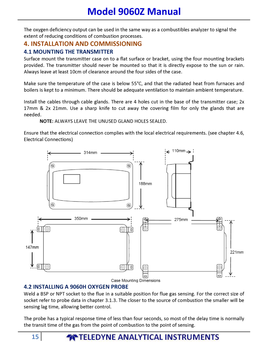
Surface mount the transmitter case on to a flat surface or bracket, using the four mounting brackets provided. The transmitter should never be mounted so that it is directly expose to the sun or rain. Always leave at least 10cm of clearance around the four sides of the case.
Make sure the temperature of the case is below 55°C, and that the radiated heat from furnaces and boilers is kept to a minimum. There should be adequate ventilation to maintain ambient temperature.
Install the cables through cable glands. There are 4 holes cut in the base of the transmitter case; 2x 17mm & 2x 21mm. Use a sharp knife to cut away the covering film for only the glands that are needed.
NOTE: ALWAYS LEAVE THE UNUSED GLAND HOLES SEALED.
Ensure that the electrical connection complies with the local electrical requirements. (see chapter 4.6, Electrical Connections)
4.2 INSTALLING A 9060H OXYGEN PROBE
Weld a BSP or NPT socket to the flue in a suitable position for flue gas sensing. For the correct size of socket refer to probe data in chapter 3.1.3. The closer to the source of combustion the smaller will be sensing lag time, allowing better control.
The probe has a typical response time of less than four seconds, so most of the delay time is normally the transit time of the gas from the point of combustion to the point of sensing.
15
