Model 9060Z Manual
•The mains power must be either 100/110VAC or 220/240VAC with a mains frequency of 50 or 60Hz
•The supply circuit must be fused to at least 10Amps and have a dual pole isolation switch within easy access of the oxygen transmitter. The isolation switch must be marked as the isolation switch for this equipment. It is recommended that a separate isolation switch be used for each transmitter so that a transmitter can be serviced individually.
•The power supply cables must be supplied and installed according to local regulations
•The earth connection must comply with the local regulations must have a current carrying capability
∙equal or greater than the supply fuse current rating
•The earth connection must be connected to the primary earth stud inside the transmitter on the right hand side
•All other bonded earth connections from the external wiring must be connected to the primary earth stud.
All operations relating the electrical wiring and installation must be carried out by qualified persons in accordance with the safety regulations and the wiring rules.
NOTE: The power switch in the transmitter can be used to turn off the transmitter. There must be an approved isolation device installed to provide complete isolation of the mains power to the transmitter. The mains wiring terminal must not be used as an disconnect device.
4.6 HEATER INTERLOCK RELAYS
CAUTION
Explosion protection for heated probes is achieved by switching the power to the probe heater off whenever the main fuel valve is closed.
The principle of safety is that if the main fuel valve is open then main flame has been established. With this primary source of ignition on, the probe heater can be safely switched on. The most dangerous situation is if fuel leaks into the combustion appliance when the fuel valve is closed. When power is removed from the main fuel valve the heater should also be switched off.
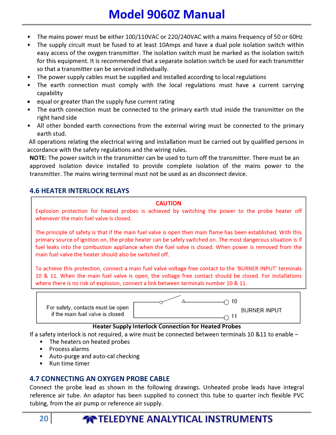
To achieve this protection, connect a main fuel valve voltage free contact to the ‘BURNER INPUT’ terminals 10 & 11. When the main fuel valve is open, the voltage free contact should be closed. For installations where there is no risk of explosion, connect a link between terminals number 10 & 11.
Heater Supply Interlock Connection for Heated Probes
If a safety interlock is not required, a wire must be connected between terminals 10 &11 to enable –
•The heaters on heated probes
•Process alarms
•Auto‐purge and auto‐cal checking
•Run time timer
4.7CONNECTING AN OXYGEN PROBE CABLE
Connect the probe lead as shown in the following drawings. Unheated probe leads have integral reference air tube. An adaptor has been supplied to connect this tube to quarter inch flexible PVC tubing, from the air pump or reference air supply.
20