Model 9060Z Manual
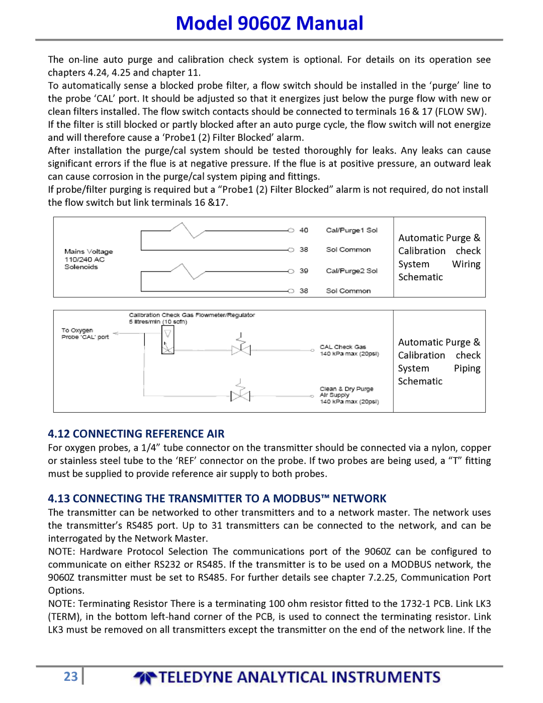
The on‐line auto purge and calibration check system is optional. For details on its operation see chapters 4.24, 4.25 and chapter 11.
To automatically sense a blocked probe filter, a flow switch should be installed in the ‘purge’ line to the probe ‘CAL’ port. It should be adjusted so that it energizes just below the purge flow with new or clean filters installed. The flow switch contacts should be connected to terminals 16 & 17 (FLOW SW). If the filter is still blocked or partly blocked after an auto purge cycle, the flow switch will not energize and will therefore cause a ‘Probe1 (2) Filter Blocked’ alarm.
After installation the purge/cal system should be tested thoroughly for leaks. Any leaks can cause significant errors if the flue is at negative pressure. If the flue is at positive pressure, an outward leak can cause corrosion in the purge/cal system piping and fittings.
If probe/filter purging is required but a “Probe1 (2) Filter Blocked” alarm is not required, do not install the flow switch but link terminals 16 &17.
Automatic Purge &
Calibration check
System Wiring
Schematic
Automatic Purge &
Calibration check
System Piping
Schematic
4.12 CONNECTING REFERENCE AIR
For oxygen probes, a 1/4” tube connector on the transmitter should be connected via a nylon, copper or stainless steel tube to the ‘REF’ connector on the probe. If two probes are being used, a “T” fitting must be supplied to provide reference air supply to both probes.
4.13 CONNECTING THE TRANSMITTER TO A MODBUS™ NETWORK
The transmitter can be networked to other transmitters and to a network master. The network uses the transmitter’s RS485 port. Up to 31 transmitters can be connected to the network, and can be interrogated by the Network Master.
NOTE: Hardware Protocol Selection The communications port of the 9060Z can be configured to communicate on either RS232 or RS485. If the transmitter is to be used on a MODBUS network, the 9060Z transmitter must be set to RS485. For further details see chapter 7.2.25, Communication Port Options.
NOTE: Terminating Resistor There is a terminating 100 ohm resistor fitted to the 1732‐1 PCB. Link LK3 (TERM), in the bottom left‐hand corner of the PCB, is used to connect the terminating resistor. Link LK3 must be removed on all transmitters except the transmitter on the end of the network line. If the
23
