Manuals
/
Teledyne
/
Personal Care
/
Oxygen Equipment
Teledyne
manual
Model 9060Z Manual
Models:
9060Z
1
64
67
67
Download
67 pages
8.33 Kb
60
61
62
63
64
65
66
67
Troubleshooting
Install
Output load Alarm relays
Heater SSR Fault Correction
Connecting the Output Channels
Maintenance
Serial Configuration
Setup Mode
Temperature Range
Onnecting Power
Page 64
Image 64
Model 9060Z Manual
64
Page 63
Page 65
Page 64
Image 64
Page 63
Page 65
Contents
Teledyne Analytical Instruments
Model 9060Z Manual
Keypad
Forcing a Cold Start Resetting the Calibration Factors
Purge
Email asktai@teledyne.com
Important Notice Regarding 9060 Probe Option ‐ FIL‐3
Important Notices
9060Z Transmitter
Introduction
Series 9060H Oxygen Probes & Sensors
Model 9060Z Manual
Temperature accuracy
Output load Alarm relays
Alarm relay contacts
Power
Temperature Range
Head Temperature
Connection Weight
9060H 9060UL/UH Application
Heated probes‐temperature range 0‐900C 1650F
Model 9060Z Manual
Function Minimum Maximum
Range of outputs
Installing a 9060H Oxygen Probe
Installation and Commissioning
Mounting the Transmitter
Oxygen Probe Mounting
Installing the Auxiliary Thermocouple
4A Shield Connections
4B Earth Connection PE
Electrical Connections
Model 9060Z Manual
Model 9060Z Manual
Heater Interlock Relays
Connecting AN Oxygen Probe Cable
Heater Supply Interlock Connection for Heated Probes
Model 9060Z Manual
Connecting the Auxiliary Thermocouple Optional
Connecting the Output Channels
Connecting the Alarms
Connecting the Automatic Purge and Calibration Check System
Connecting Reference AIR
Connecting the Transmitter to a Modbus Network
Onnecting Power
Commissioning ‐ RUN Mode
Probe or Sensor Calibration
For more details see Appendix
Calibration GAS Check
Filter Purging
Dust in the Flue GAS
Connecting a Pressure Transducer
Stratification
Display and Keypad
Graphical Display
Keypad in RUN mode
Key text RUN mode White text Setup mode Black text
Oxygen Display Units
Keypad
Keypad in Setup / Commissioning / Calibration modes
Function up and Function down keys
Option up and Option down keys
Enter key
Probe impedance key
Setup Mode
Function Summary Table
Changing Options
Function name Range
Probe 1 Offset
Setup Mode Functions
Lower Line Items
Oxygen Display Units
Process Alarms
Damping Factor
Commissioning Mode
Model 9060Z Manual
Commissioning Mode Functions
Model 9060Z Manual
Temperature Units
Flue Pressure Units and Value
Calibration Freezes Outputs
Solenoid 1 & 2 Operation
Oxygen Content Calibration Gas 1
Maximum Calibration Gas 1 & 2 Positive / Negative Error
Alarm Relay 1, 2 and 3 Function
Common Alarm Relay Function
Operation of the Alarm Relays when an Alarm is Accepted
Selecting the Correct Fuel
Reference Air Pump Options
Function Options
Alarm Log Clearing
Communications Port Options
Calibration Mode
Menu Function name Range
Calibration Mode Functions
Reference Voltages
Heater SSR Fault Correction
Alarms
Common Alarms
Model 9060Z Manual
Selectable Process Alarms
Alarm Relay Options
Instrument Calibration
Calibration Summary
Probe Calibration
Cold Start
Calibration GAS
GAS Calibration Check and Purge
Function # Function Description Options
Software Upgrades
Detailed Fault Analysis
Troubleshooting
First Approach
Maintenance
Transmitter Maintenance
Cleaning
Replacement Parts
Index
Auxiliary Thermocouple
Troubleshooting
Is the H/C atom ratio in the fuel
Is the O/C atom ratio in the fuel
Is the N/C atom ratio in the fuel
Is the S/C atom ratio in the fuel
Appendix 2, Probe EMF Tables
Zirconia Oxygen Sensor Output mV Probe Type 9060H, Sensor
Probe EMF
Probe EMF @ 720C 1320F
Zirconia Oxygen Probe Output mV Probe Type 9060UL/UH
13.1
20.7
26.2
33.8
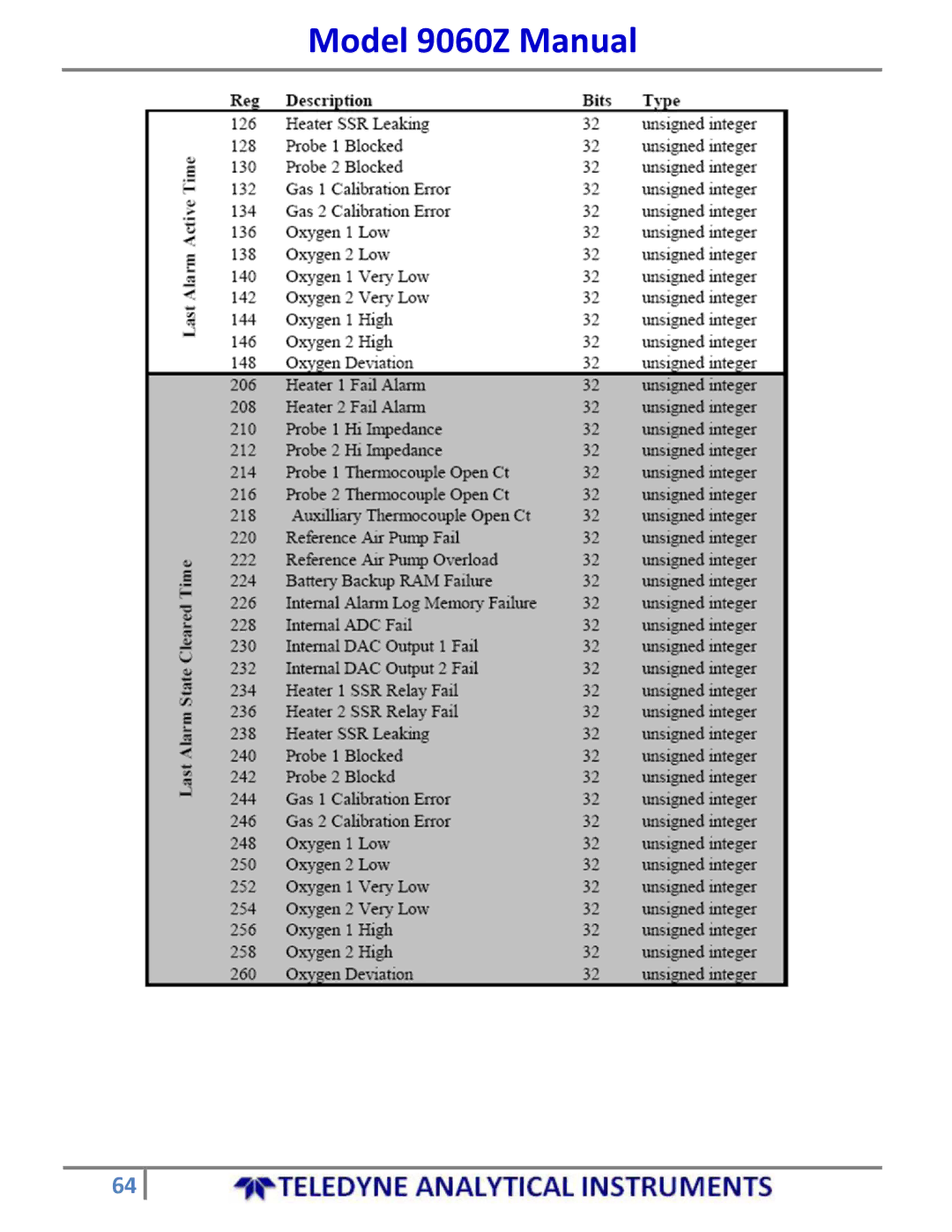
Serial Configuration
Modbus Protocol
Model 9060Z Manual
Model 9060Z Manual
Model 9060Z Manual
Model 9060Z Manual
Model 9060Z Manual
0x41 Special Instruction Function
0x02
0x03
0x04
Top
Page
Image
Contents