Peripheral Architecture | www.ti.com |
2.4.2Data Validity
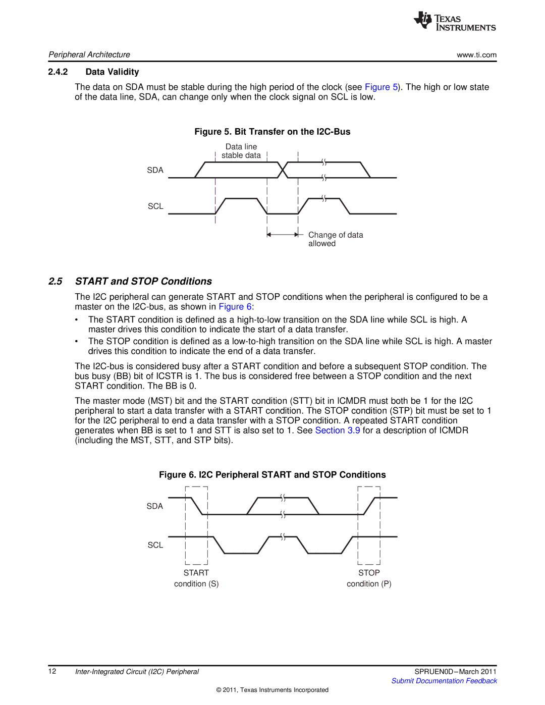
The data on SDA must be stable during the high period of the clock (see Figure 5). The high or low state of the data line, SDA, can change only when the clock signal on SCL is low.
Figure 5. Bit Transfer on the I2C-Bus
Data line
stable data
SDA
SCL
Change of data allowed
2.5START and STOP Conditions
The I2C peripheral can generate START and STOP conditions when the peripheral is configured to be a master on the
•The START condition is defined as a
•The STOP condition is defined as a
The
The master mode (MST) bit and the START condition (STT) bit in ICMDR must both be 1 for the I2C peripheral to start a data transfer with a START condition. The STOP condition (STP) bit must be set to 1 for the I2C peripheral to end a data transfer with a STOP condition. A repeated START condition generates when BB is set to 1 and STT is also set to 1. See Section 3.9 for a description of ICMDR (including the MST, STT, and STP bits).
Figure 6. I2C Peripheral START and STOP Conditions
SDA
SCL
START | STOP |
condition (S) | condition (P) |
12 | SPRUEN0D | |
|
| Submit Documentation Feedback |
© 2011, Texas Instruments Incorporated
