www.ti.com | Registers |
3.11 I2C Extended Mode Register (ICEMDR)
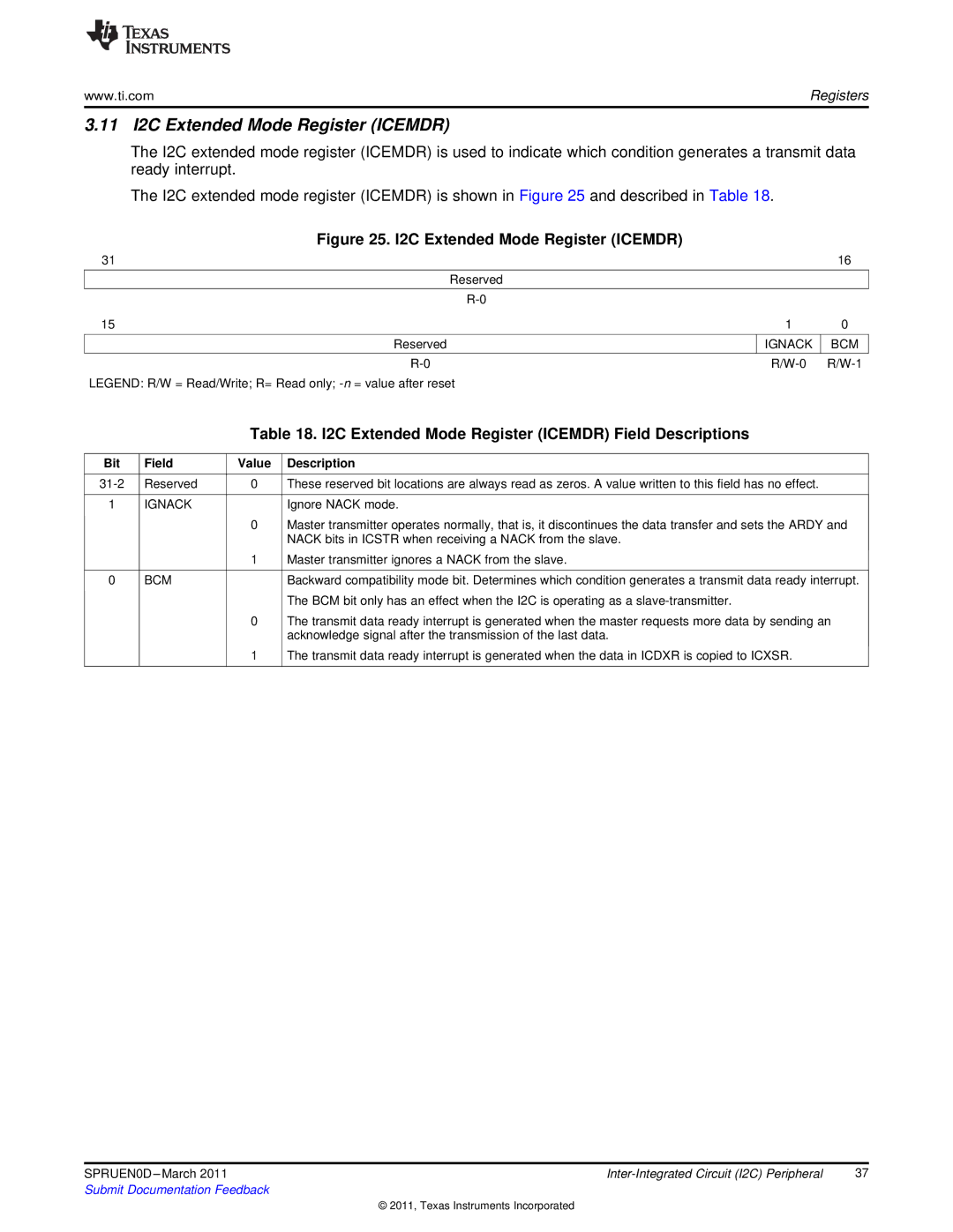
The I2C extended mode register (ICEMDR) is used to indicate which condition generates a transmit data ready interrupt.
The I2C extended mode register (ICEMDR) is shown in Figure 25 and described in Table 18.
Figure 25. I2C Extended Mode Register (ICEMDR)
31
Reserved
15
Reserved
LEGEND: R/W = Read/Write; R= Read only;
16
10
IGNACK BCM R/W-0 R/W-1
Table 18. I2C Extended Mode Register (ICEMDR) Field Descriptions
Bit | Field | Value | Description |
|
|
|
|
Reserved | 0 | These reserved bit locations are always read as zeros. A value written to this field has no effect. | |
|
|
|
|
1 | IGNACK |
| Ignore NACK mode. |
|
| 0 | Master transmitter operates normally, that is, it discontinues the data transfer and sets the ARDY and |
|
|
| NACK bits in ICSTR when receiving a NACK from the slave. |
|
| 1 | Master transmitter ignores a NACK from the slave. |
|
|
|
|
0 | BCM |
| Backward compatibility mode bit. Determines which condition generates a transmit data ready interrupt. |
|
|
| The BCM bit only has an effect when the I2C is operating as a |
|
| 0 | The transmit data ready interrupt is generated when the master requests more data by sending an |
|
|
| acknowledge signal after the transmission of the last data. |
|
| 1 | The transmit data ready interrupt is generated when the data in ICDXR is copied to ICXSR. |
|
|
|
|
SPRUEN0D | 37 | |
Submit Documentation Feedback |
|
|
© 2011, Texas Instruments Incorporated
