Peripheral Architecture | www.ti.com |
2.6.210-Bit Addressing Format
The
Write 1 to the XA bit of ICMDR to select the
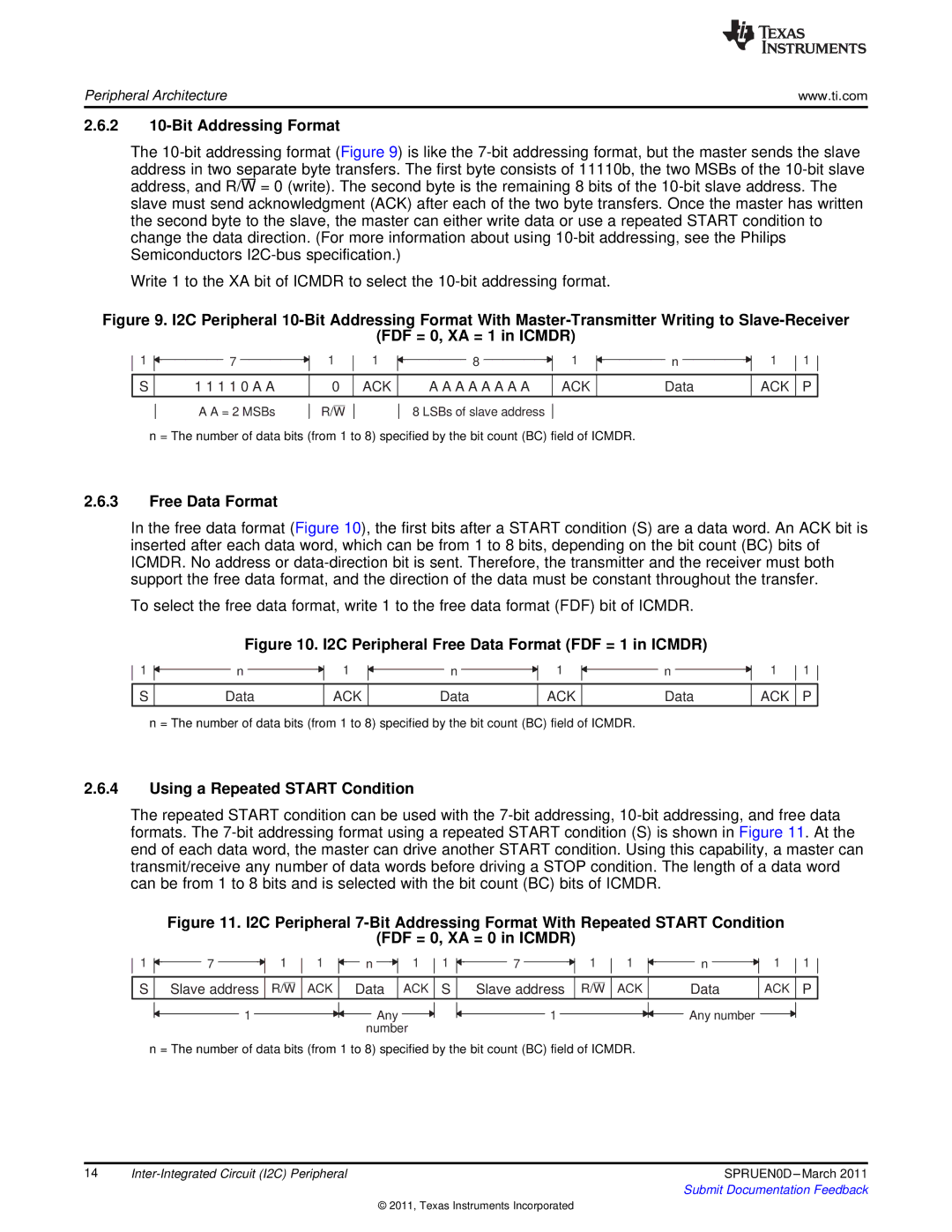
Figure 9. I2C Peripheral 10-Bit Addressing Format With Master-Transmitter Writing to Slave-Receiver
(FDF = 0, XA = 1 in ICMDR)
1
7
1
1
8
1
n
1
1
S
1 1 1 1 0 A A
0
ACK
A A A A A A A A
ACK
Data
ACK P
A A = 2 MSBs
R/W
8 LSBs of slave address
n = The number of data bits (from 1 to 8) specified by the bit count (BC) field of ICMDR.
2.6.3Free Data Format
In the free data format (Figure 10), the first bits after a START condition (S) are a data word. An ACK bit is inserted after each data word, which can be from 1 to 8 bits, depending on the bit count (BC) bits of ICMDR. No address or
To select the free data format, write 1 to the free data format (FDF) bit of ICMDR.
Figure 10. I2C Peripheral Free Data Format (FDF = 1 in ICMDR)
1
n
1
n
1
n
1
1
S
Data
ACK
Data
ACK
Data
ACK P
n = The number of data bits (from 1 to 8) specified by the bit count (BC) field of ICMDR.
2.6.4Using a Repeated START Condition
The repeated START condition can be used with the
Figure 11. I2C Peripheral 7-Bit Addressing Format With Repeated START Condition
(FDF = 0, XA = 0 in ICMDR)
1 | 7 | 1 | 1 | n | 1 | 1 | 7 | 1 | 1 | n | 1 | 1 |
S | Slave address | R/W | ACK | Data | ACK | S | Slave address | R/W | ACK | Data | ACK | P |
1 | Any | 1 |
| number |
|
n = The number of data bits (from 1 to 8) specified by the bit count (BC) field of ICMDR.
Any number ![]()
14 | SPRUEN0D | |
|
| Submit Documentation Feedback |
© 2011, Texas Instruments Incorporated