www.ti.comRegisters
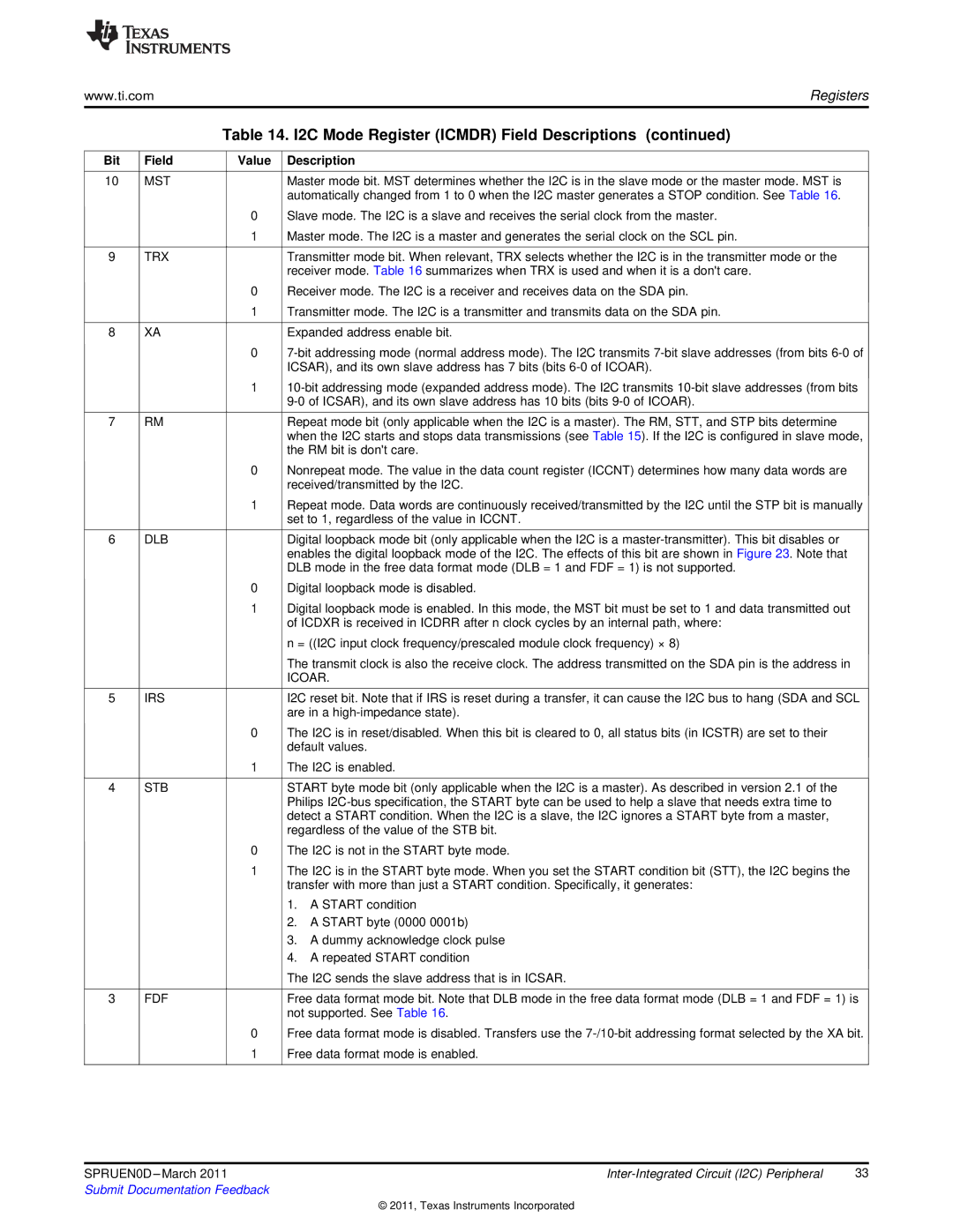
Table 14. I2C Mode Register (ICMDR) Field Descriptions (continued)
Bit | Field | Value | Description |
|
|
|
|
10 | MST |
| Master mode bit. MST determines whether the I2C is in the slave mode or the master mode. MST is |
|
|
| automatically changed from 1 to 0 when the I2C master generates a STOP condition. See Table 16. |
|
| 0 | Slave mode. The I2C is a slave and receives the serial clock from the master. |
|
| 1 | Master mode. The I2C is a master and generates the serial clock on the SCL pin. |
|
|
|
|
9 | TRX |
| Transmitter mode bit. When relevant, TRX selects whether the I2C is in the transmitter mode or the |
|
|
| receiver mode. Table 16 summarizes when TRX is used and when it is a don't care. |
|
| 0 | Receiver mode. The I2C is a receiver and receives data on the SDA pin. |
|
| 1 | Transmitter mode. The I2C is a transmitter and transmits data on the SDA pin. |
|
|
|
|
8 | XA |
| Expanded address enable bit. |
|
| 0 | |
|
|
| ICSAR), and its own slave address has 7 bits (bits |
|
| 1 | |
|
|
| |
|
|
|
|
7 | RM |
| Repeat mode bit (only applicable when the I2C is a master). The RM, STT, and STP bits determine |
|
|
| when the I2C starts and stops data transmissions (see Table 15). If the I2C is configured in slave mode, |
|
|
| the RM bit is don't care. |
|
| 0 | Nonrepeat mode. The value in the data count register (ICCNT) determines how many data words are |
|
|
| received/transmitted by the I2C. |
|
| 1 | Repeat mode. Data words are continuously received/transmitted by the I2C until the STP bit is manually |
|
|
| set to 1, regardless of the value in ICCNT. |
|
|
|
|
6 | DLB |
| Digital loopback mode bit (only applicable when the I2C is a |
|
|
| enables the digital loopback mode of the I2C. The effects of this bit are shown in Figure 23. Note that |
|
|
| DLB mode in the free data format mode (DLB = 1 and FDF = 1) is not supported. |
|
| 0 | Digital loopback mode is disabled. |
|
| 1 | Digital loopback mode is enabled. In this mode, the MST bit must be set to 1 and data transmitted out |
|
|
| of ICDXR is received in ICDRR after n clock cycles by an internal path, where: |
|
|
| n = ((I2C input clock frequency/prescaled module clock frequency) × 8) |
|
|
| The transmit clock is also the receive clock. The address transmitted on the SDA pin is the address in |
|
|
| ICOAR. |
|
|
|
|
5 | IRS |
| I2C reset bit. Note that if IRS is reset during a transfer, it can cause the I2C bus to hang (SDA and SCL |
|
|
| are in a |
|
| 0 | The I2C is in reset/disabled. When this bit is cleared to 0, all status bits (in ICSTR) are set to their |
|
|
| default values. |
|
| 1 | The I2C is enabled. |
|
|
|
|
4 | STB |
| START byte mode bit (only applicable when the I2C is a master). As described in version 2.1 of the |
|
|
| Philips |
|
|
| detect a START condition. When the I2C is a slave, the I2C ignores a START byte from a master, |
|
|
| regardless of the value of the STB bit. |
|
| 0 | The I2C is not in the START byte mode. |
|
| 1 | The I2C is in the START byte mode. When you set the START condition bit (STT), the I2C begins the |
|
|
| transfer with more than just a START condition. Specifically, it generates: |
|
|
| 1. A START condition |
|
|
| 2. A START byte (0000 0001b) |
|
|
| 3. A dummy acknowledge clock pulse |
|
|
| 4. A repeated START condition |
|
|
| The I2C sends the slave address that is in ICSAR. |
|
|
|
|
3 | FDF |
| Free data format mode bit. Note that DLB mode in the free data format mode (DLB = 1 and FDF = 1) is |
|
|
| not supported. See Table 16. |
|
| 0 | Free data format mode is disabled. Transfers use the |
|
| 1 | Free data format mode is enabled. |
|
|
|
|
SPRUEN0D | 33 | |
Submit Documentation Feedback |
|
|
© 2011, Texas Instruments Incorporated