Texas Instruments TMS320C642X manual 3.6I2C Data Receive Register ICDRR

Models: TMS320C642X

1 41
Download 41 pages 39.49 Kb
Page 30
Image 30
3.6I2C Data Receive Register (ICDRR)

Registers

www.ti.com

3.6I2C Data Receive Register (ICDRR)

The I2C data receive register (ICDRR) is used to read the receive data. The ICDRR can receive a data value of up to 8 bits; data values with fewer than 8 bits are right-aligned in the D bits and the remaining D bits are undefined. The number of data bits is selected by the bit count bits (BC) of ICMDR. The I2C receive shift register (ICRSR) shifts in the received data from the SDA pin. Once data is complete, the I2C copies the contents of ICRSR into ICDRR. The CPU and the EDMA controller cannot access ICRSR.

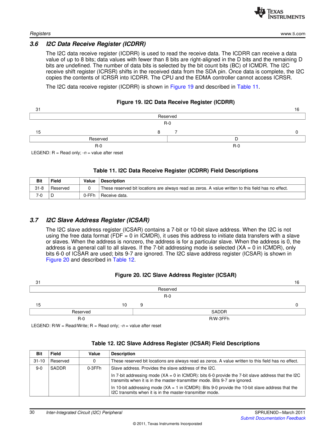
The I2C data receive register (ICDRR) is shown in Figure 19 and described in Table 11.

Figure 19. I2C Data Receive Register (ICDRR)

31


16


Reserved


R-0


15

8

7

0


Reserved


D


R-0


R-0

LEGEND: R = Read only; -n= value after reset

Table 11. I2C Data Receive Register (ICDRR) Field Descriptions

Bit

Field

Value

Description


31-8

Reserved

0

These reserved bit locations are always read as zeros. A value written to this field has no effect.


7-0

D

0-FFh

Receive data.


3.7I2C Slave Address Register (ICSAR)

The I2C slave address register (ICSAR) contains a 7-bit or 10-bit slave address. When the I2C is not using the free data format (FDF = 0 in ICMDR), it uses this address to initiate data transfers with a slave or slaves. When the address is nonzero, the address is for a particular slave. When the address is 0, the address is a general call to all slaves. If the 7-bit addressing mode is selected (XA = 0 in ICMDR), only bits 6-0 of ICSAR are used; bits 9-7 are ignored. The I2C slave address register (ICSAR) is shown in Figure 20 and described in Table 12.

Figure 20. I2C Slave Address Register (ICSAR)

31


16


Reserved


R-0

15

10

9

0


Reserved


SADDR


R-0


R/W-3FFh

LEGEND: R/W = Read/Write; R = Read only; -n= value after reset

Table 12. I2C Slave Address Register (ICSAR) Field Descriptions

Bit


Field

Value

Description


31-10


Reserved

0

These reserved bit locations are always read as zeros. A value written to this field has no effect.


9-0


SADDR

0-3FFh

Slave address. Provides the slave address of the I2C.


In 7-bit addressing mode (XA = 0 in ICMDR): bits 6-0 provide the 7-bit slave address that the I2C


transmits when it is in the master-transmitter mode. Bits 9-7 are ignored.


In 10-bit addressing mode (XA = 1 in ICMDR): Bits 9-0 provide the 10-bit slave address that the


I2C transmits when it is in the master-transmitter mode.


30

Inter-Integrated Circuit (I2C) Peripheral

SPRUEN0D –March 2011


Submit Documentation Feedback

© 2011, Texas Instruments Incorporated

Page 30
Image 30
Texas Instruments TMS320C642X manual 3.6I2C Data Receive Register ICDRR, 3.7I2C Slave Address Register ICSAR