Registerswww.ti.com
Table 14. I2C Mode Register (ICMDR) Field Descriptions (continued)
Bit | Field | Value | Description |
|
|
|
|
BC | Bit count bits. BC defines the number of bits (1 to 8) in the next data word that is to be received or | ||
|
|
| transmitted by the I2C. The number of bits selected with BC must match the data size of the other |
|
|
| device. Note that when BC = 0, a data word has 8 bits. |
|
|
| If the bit count is less than 8, receive data is right aligned in the D bits of ICDRR and the remaining D |
|
|
| bits are undefined. Also, transmit data written to ICDXR must be right aligned. |
|
| 0 | 8 bits per data word |
|
| 1h | 1 bit per data word |
|
| 2h | 2 bits per data word |
|
| 3h | 3 bits per data word |
|
| 4h | 4 bits per data word |
|
| 5h | 5 bits per data word |
|
| 6h | 6 bits per data word |
|
| 7h | 7 bits per data word |
|
|
|
|
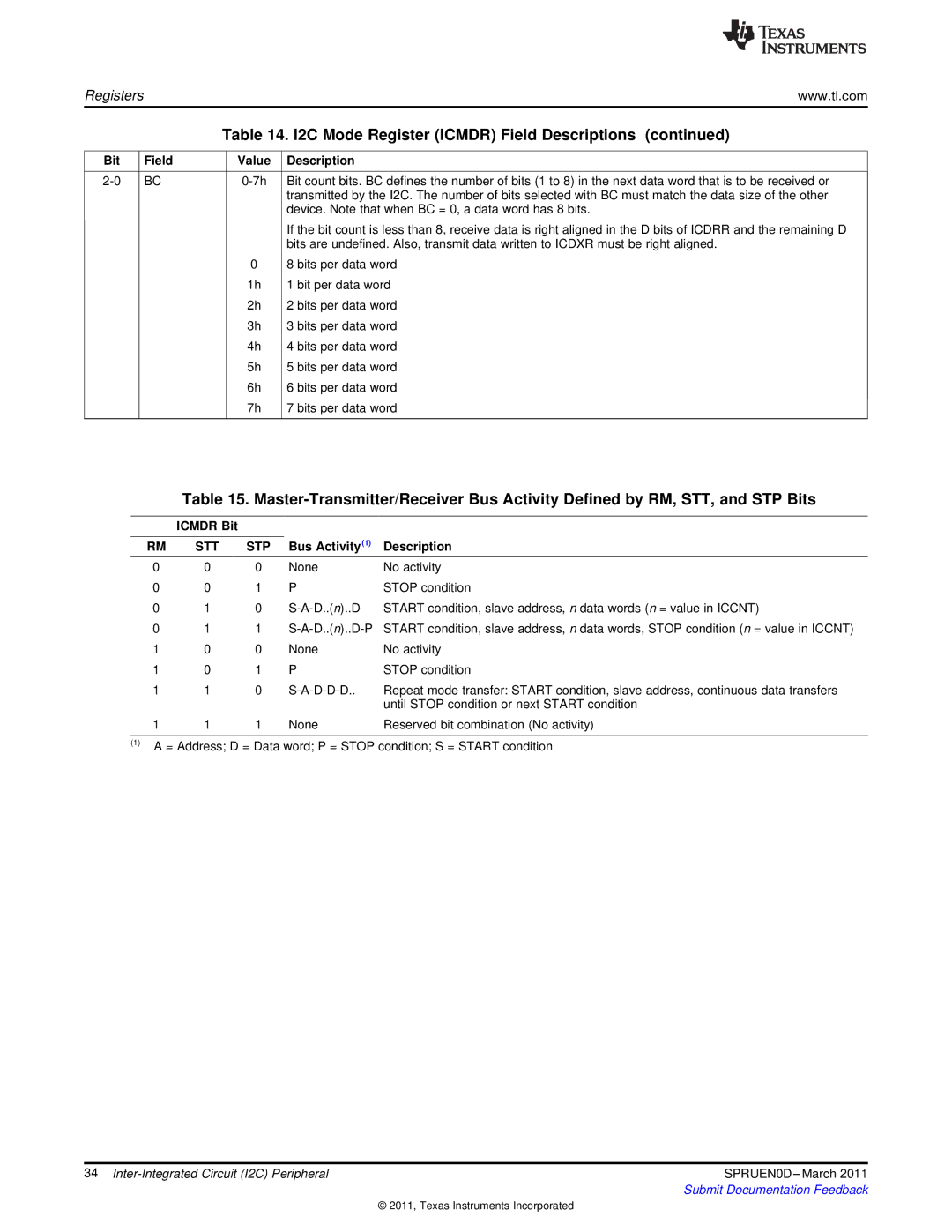
Table 15.
| ICMDR Bit |
|
|
|
RM | STT | STP | Bus Activity(1) | Description |
0 | 0 | 0 | None | No activity |
0 | 0 | 1 | P | STOP condition |
0 | 1 | 0 | START condition, slave address, n data words (n = value in ICCNT) | |
0 | 1 | 1 | START condition, slave address, n data words, STOP condition (n = value in ICCNT) | |
1 | 0 | 0 | None | No activity |
1 | 0 | 1 | P | STOP condition |
1 | 1 | 0 | Repeat mode transfer: START condition, slave address, continuous data transfers | |
|
|
|
| until STOP condition or next START condition |
1 | 1 | 1 | None | Reserved bit combination (No activity) |
(1)A = Address; D = Data word; P = STOP condition; S = START condition
34 | SPRUEN0D |
| Submit Documentation Feedback |
© 2011, Texas Instruments Incorporated
