www.ti.com

Peripheral Architecture

Once in self-refresh mode, the DDR2 memory controller input clocks (VCLK and X2_CLK) may be gated off or changed in frequency. Stable clocks must be present before exiting self-refresh mode. See Section 2.16 for more information describing the proper procedure to follow when shutting down DDR2 memory controller input clocks.

2.11 Reset Considerations

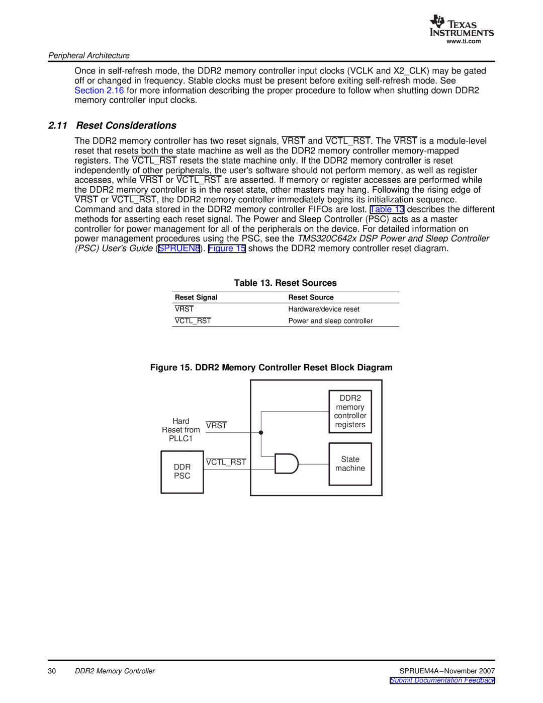
The DDR2 memory controller has two reset signals, VRST and VCTL_RST. The VRST is a module-level reset that resets both the state machine as well as the DDR2 memory controller memory-mapped registers. The VCTL_RST resets the state machine only. If the DDR2 memory controller is reset independently of other peripherals, the user's software should not perform memory, as well as register accesses, while VRST or VCTL_RST are asserted. If memory or register accesses are performed while the DDR2 memory controller is in the reset state, other masters may hang. Following the rising edge of VRST or VCTL_RST, the DDR2 memory controller immediately begins its initialization sequence. Command and data stored in the DDR2 memory controller FIFOs are lost. Table 13 describes the different methods for asserting each reset signal. The Power and Sleep Controller (PSC) acts as a master controller for power management for all of the peripherals on the device. For detailed information on power management procedures using the PSC, see the TMS320C642x DSP Power and Sleep Controller (PSC) User's Guide (SPRUEN8). Figure 15 shows the DDR2 memory controller reset diagram.


Table 13. Reset Sources

Reset Signal

Reset Source

VRST

Hardware/device reset

VCTL_RST

Power and sleep controller

Figure 15. DDR2 Memory Controller Reset Block Diagram

Hard

Reset from

PLLC1

DDR

PSC

VRST

VCTL_RST

DDR2

memory controller registers

State

machine

30

DDR2 Memory Controller

SPRUEM4A–November 2007

Submit Documentation Feedback

Page 30
Image 30
Texas Instruments TMS320C642x DSP manual Reset Considerations, Reset Sources, Reset Signal Reset Source