Texas Instruments TMS320C642x DSP manual Interrupt Support, DMA Event Support, Power Management

Models: TMS320C642x DSP

1 57
Download 57 pages 6.18 Kb
Page 34
Image 34
2.14 Interrupt Support

www.ti.com

Peripheral Architecture

2.14 Interrupt Support

The DDR2 memory controller supports two addressing modes, linear incrementing and cache line wrap. Upon receipt of an access request for an unsupported addressing mode, the DDR2 memory controller generates an interrupt by setting the LT bit in the interrupt raw register (IRR). The DDR2 memory controller will then treat the request as a linear incrementing request.

This interrupt is called the line trap interrupt and is the only interrupt the DDR2 memory controller supports. It is an active-high interrupt and is enabled by the LTMSET bit in the interrupt mask set register (IMSR). This interrupt is mapped to both the DSP and the ARM and is not multiplexed with other interrupts.

2.15 DMA Event Support

The DDR2 memory controller is a DMA slave peripheral and therefore does not generate DMA events. Data read and write requests may be made directly by masters and by the DMA.

2.16 Power Management

Power dissipation from the DDR2 memory controller may be managed by two methods:

Self-refresh mode (see Section 2.10)

Gating input clocks to the module off

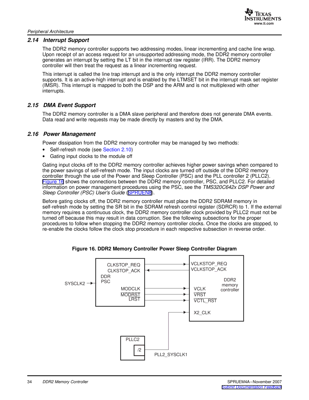
Gating input clocks off to the DDR2 memory controller achieves higher power savings when compared to the power savings of self-refresh mode. The input clocks are turned off outside of the DDR2 memory controller through the use of the Power and Sleep Controller (PSC) and the PLL controller 2 (PLLC2). Figure 16 shows the connections between the DDR2 memory controller, PSC, and PLLC2. For detailed information on power management procedures using the PSC, see the TMS320C642x DSP Power and Sleep Controller (PSC) User's Guide (SPRUEN8).

Before gating clocks off, the DDR2 memory controller must place the DDR2 SDRAM memory in self-refresh mode by setting the SR bit in the SDRAM refresh control register (SDRCR) to 1. If the external memory requires a continuous clock, the DDR2 memory controller clock provided by PLLC2 must not be turned off because this may result in data corruption. See the following subsections for the proper procedures to follow when stopping the DDR2 memory controller clocks. Once the clocks are stopped, to re-enable the clocks follow the clock stop procedure in each respective subsection in reverse order.

Figure 16. DDR2 Memory Controller Power Sleep Controller Diagram

CLKSTOP_REQ

CLKSTOP_ACK


DDR

SYSCLK2


PSC


MODCLK

MODRST

LRST

PLLC2

/2

VCLKSTOP_REQ

VCLKSTOP_ACK

DDR2

memory

VCLK controller

VRST

VCTL_RST

X2_CLK

PLL2_SYSCLK1

34

DDR2 Memory Controller

SPRUEM4A–November 2007

Submit Documentation Feedback

Page 34
Image 34
Texas Instruments TMS320C642x DSP manual Interrupt Support, DMA Event Support, Power Management