www.ti.com
DDR2 Memory Controller Registers
4DDR2 Memory Controller Registers
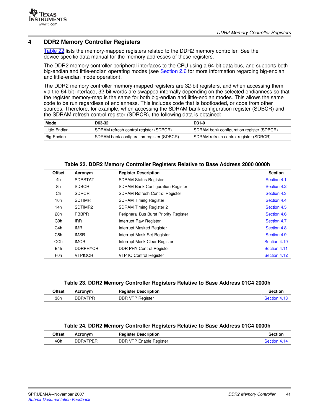
Table 22 lists the
The DDR2 memory controller peripheral interfaces to the CPU using a
The DDR2 memory controller
Mode |
|
SDRAM refresh control register (SDRCR) | |
SDRAM bank configuration register (SDBCR) |

D31-0
SDRAM bank configuration register (SDBCR)
![]() SDRAM refresh control register (SDRCR)
SDRAM refresh control register (SDRCR)
Table 22. DDR2 Memory Controller Registers Relative to Base Address 2000 0000h
Offset | Acronym | Register Description | Section |
4h | SDRSTAT | SDRAM Status Register | Section 4.1 |
8h | SDBCR | SDRAM Bank Configuration Register | Section 4.2 |
Ch | SDRCR | SDRAM Refresh Control Register | Section 4.3 |
10h | SDTIMR | SDRAM Timing Register | Section 4.4 |
14h | SDTIMR2 | SDRAM Timing Register 2 | Section 4.5 |
20h | PBBPR | Peripheral Bus Burst Priority Register | Section 4.6 |
C0h | IRR | Interrupt Raw Register | Section 4.7 |
C4h | IMR | Interrupt Masked Register | Section 4.8 |
C8h | IMSR | Interrupt Mask Set Register | Section 4.9 |
CCh | IMCR | Interrupt Mask Clear Register | Section 4.10 |
E4h | DDRPHYCR | DDR PHY Control Register | Section 4.11 |
F0h | VTPIOCR | VTP IO Control Register | Section 4.12 |
Table 23. DDR2 Memory Controller Registers Relative to Base Address 01C4 2000h
Offset | Acronym | Register Description | Section |
38h | DDRVTPR | DDR VTP Register | Section 4.13 |
Table 24. DDR2 Memory Controller Registers Relative to Base Address 01C4 0000h
Offset | Acronym | Register Description | Section |
4Ch | DDRVTPER | DDR VTP Enable Register | Section 4.14 |
DDR2 Memory Controller | 41 | |
Submit Documentation Feedback |
|
|
