Sample Assembly Code to Erase and Reprogram the TMS320F240
PRELIMINARY
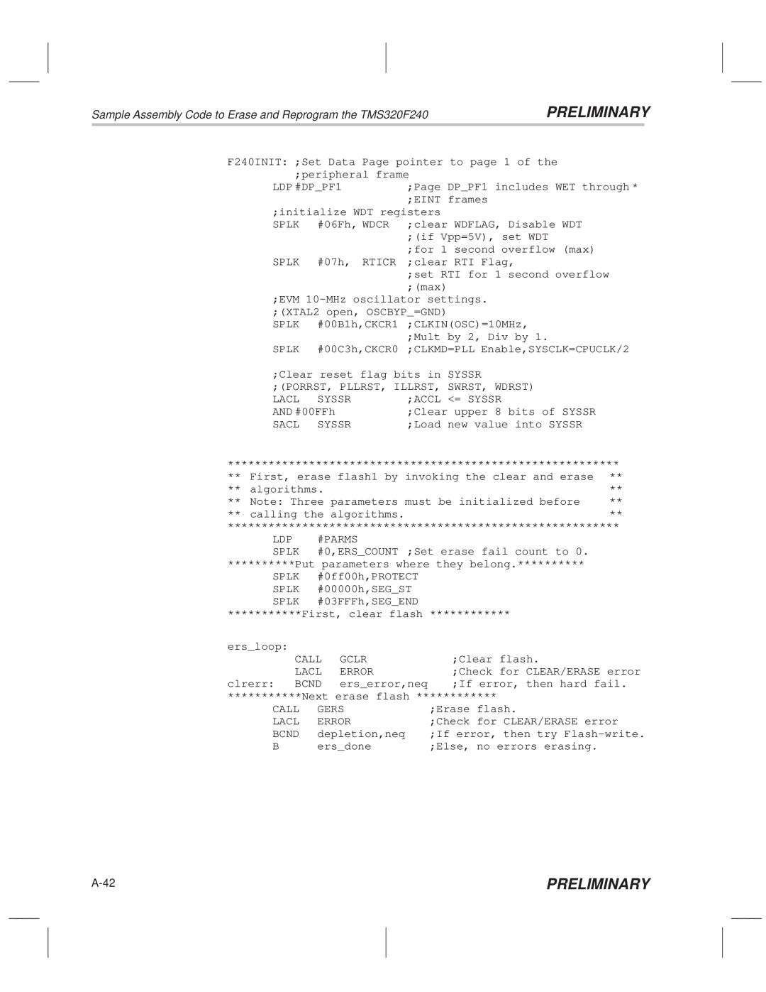
F240INIT: ;Set Data Page pointer to page 1 of the ;peripheral frame
LDP #DP_PF1 | ;Page DP_PF1 includes WET through * | |
|
| ;EINT frames |
;initialize WDT registers | ||
SPLK | #06Fh, WDCR | ;clear WDFLAG, Disable WDT |
|
| ;(if Vpp=5V), set WDT |
|
| ;for 1 second overflow (max) |
SPLK | #07h, RTICR | ;clear RTI Flag, |
|
| ;set RTI for 1 second overflow |
|
| ;(max) |
;EVM 10±MHz oscillator settings. ;(XTAL2 open, OSCBYP_=GND)
SPLK #00B1h,CKCR1 ;CLKIN(OSC)=10MHz, ;Mult by 2, Div by 1.
SPLK #00C3h,CKCR0 ;CLKMD=PLL Enable,SYSCLK=CPUCLK/2
;Clear reset flag bits in | SYSSR | ||
;(PORRST, PLLRST, ILLRST, | SWRST, WDRST) | ||
LACL | SYSSR | ;ACCL | <= SYSSR |
AND #00FFh | ;Clear upper 8 bits of SYSSR | ||
SACL | SYSSR | ;Load new value into SYSSR | |
**********************************************************
** | First, erase flash1 by invoking the clear and erase | ** |
** | algorithms. | ** |
** | Note: Three parameters must be initialized before | ** |
** | calling the algorithms. | ** |
**********************************************************
LDP | #PARMS |
SPLK | #0,ERS_COUNT ;Set erase fail count to 0. |
**********Put parameters where they belong.**********
SPLK #0ff00h,PROTECT SPLK #00000h,SEG_ST SPLK #03FFFh,SEG_END
***********First, clear flash ************
ers_loop: |
|
|
CALL | GCLR | ;Clear flash. |
LACL | ERROR | ;Check for CLEAR/ERASE error |
clrerr: BCND | ers_error,neq | ;If error, then hard fail. |
***********Next erase flash ************
CALL | GERS | ;Erase flash. |
LACL | ERROR | ;Check for CLEAR/ERASE error |
BCND | depletion,neq | ;If error, then try Flash±write. |
B | ers_done | ;Else, no errors erasing. |
PRELIMINARY |
