|
|
|
|
|
|
|
|
|
|
|
|
|
| |||||
|
|
|
|
|
|
|
|
|
| Female | ||||||||
|
|
|
|
|
|
|
|
|
|
|
|
|
|
|
|
| ||
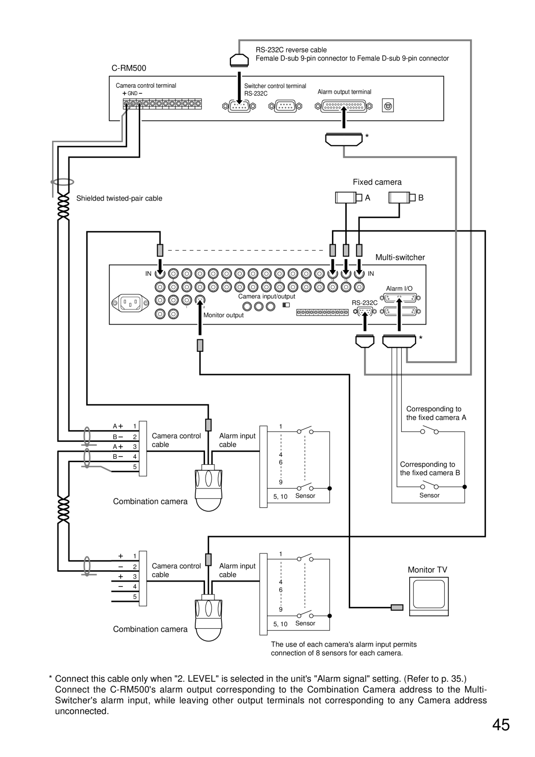
Camera control terminal |
|
|
|
|
| Switcher control terminal | Alarm output terminal |
| ||||||||||
| GND |
|
|
|
|
|
|
|
|
|
|
| ||||||
|
|
|
|
|
|
|
|
|
|
|
|
|
|
|
|
| * |
|
|
|
|
|
|
|
|
|
|
|
|
|
|
|
|
|
| Fixed camera | |
Shielded |
|
|
|
|
|
|
|
|
|
|
|
|
|
| A | B | ||
|
|
|
|
|
|
|
|
|
|
|
|
|
|
|
|
|
| |
| IN |
|
|
|
|
|
|
|
|
|
|
|
|
|
|
| IN |
|
|
| 1 | 2 | 3 | 4 | 5 | 6 | 7 | 8 | 9 | 10 | 11 | 12 | 13 | 14 | 15 | 16 |
|
|
|
|
|
|
|
|
|
|
|
|
|
|
|
|
|
|
| Alarm I/O |
|
|
|
|
|
|
|
| Camera input/output |
|
|
|
| ||||||
|
|
|
| 1 |
| 2 |
|
|
|
|
|
|
|
|
|
| ||
|
|
|
|
|
|
|
|
|
|
|
|
|
|
|
|
| ||
|
| 2 |
|
|
| Monitor output |
|
|
|
|
|
|
|
|
|
| ||
|
|
|
|
|
|
|
|
|
|
|
|
|
|
|
| |||
|
|
|
|
|
|
|
|
|
|
|
|
|
|
|
|
|
| * |
|
|
|
|
|
|
|
|
|
|
|
|
|
|
|
|
|
| Corresponding to |
|
|
|
|
|
|
|
|
|
|
|
|
|
|
|
|
|
| the fixed camera A |
A | 1 |
|
|
|
|
|
|
|
|
| 1 |
|
|
|
|
|
|
|
B | 2 | Camera control |
| Alarm input |
|
|
|
|
|
|
|
|
| |||||
A | 3 | cable |
|
|
|
| cable |
|
|
|
|
|
|
|
|
|
|
|
|
|
|
|
|
|
|
|
|
|
|
|
|
|
|
|
| ||
B | 4 |
|
|
|
|
|
|
|
|
| 4 |
|
|
|
|
|
|
|
|
|
|
|
|
|
|
|
| 6 |
|
|
|
|
|
| Corresponding to | ||
| 5 |
|
|
|
|
|
|
|
|
|
|
|
|
|
|
| ||
|
|
|
|
|
|
|
|
|
|
|
|
|
|
|
|
| the fixed camera B | |
|
|
|
|
|
|
|
|
|
|
|
|
|
|
|
|
|
| |
|
|
|
|
|
|
|
|
|
|
| 9 |
|
|
|
|
|
|
|
Combination camera |
|
|
|
|
|
| 5, 10 |
| Sensor |
|
|
|
| Sensor | ||||
|
|
|
|
|
|
|
|
|
|
|
|
|
| |||||
| 1 |
|
|
|
|
|
|
|
|
| 1 |
|
|
|
|
|
|
|
|
|
|
|
|
|
|
|
|
|
|
|
|
|
|
|
|
| |
| 2 | Camera control |
| Alarm input |
|
|
|
|
|
|
|
| Monitor TV | |||||
| 3 | cable |
|
|
|
| cable |
|
|
|
|
|
|
|
|
|
| |
|
|
|
|
|
|
|
| 4 |
|
|
|
|
|
|
| |||
| 4 |
|
|
|
|
|
|
|
|
|
|
|
|
|
|
|
| |
|
|
|
|
|
|
|
|
|
| 6 |
|
|
|
|
|
|
| |
| 5 |
|
|
|
|
|
|
|
|
|
|
|
|
|
|
|
| |
|
|
|
|
|
|
|
|
|
|
|
|
|
|
|
|
|
| |
|
|
|
|
|
|
|
|
|
|
| 9 |
|
|
|
|
|
|
|
Combination camera |
|
|
|
|
|
| 5, 10 |
| Sensor |
|
|
|
|
| ||||
|
|
|
|
|
|
|
|
|
|
|
|
|
| |||||
The use of each camera's alarm input permits connection of 8 sensors for each camera.
*Connect this cable only when "2. LEVEL" is selected in the unit's "Alarm signal" setting. (Refer to p. 35.) Connect the
45