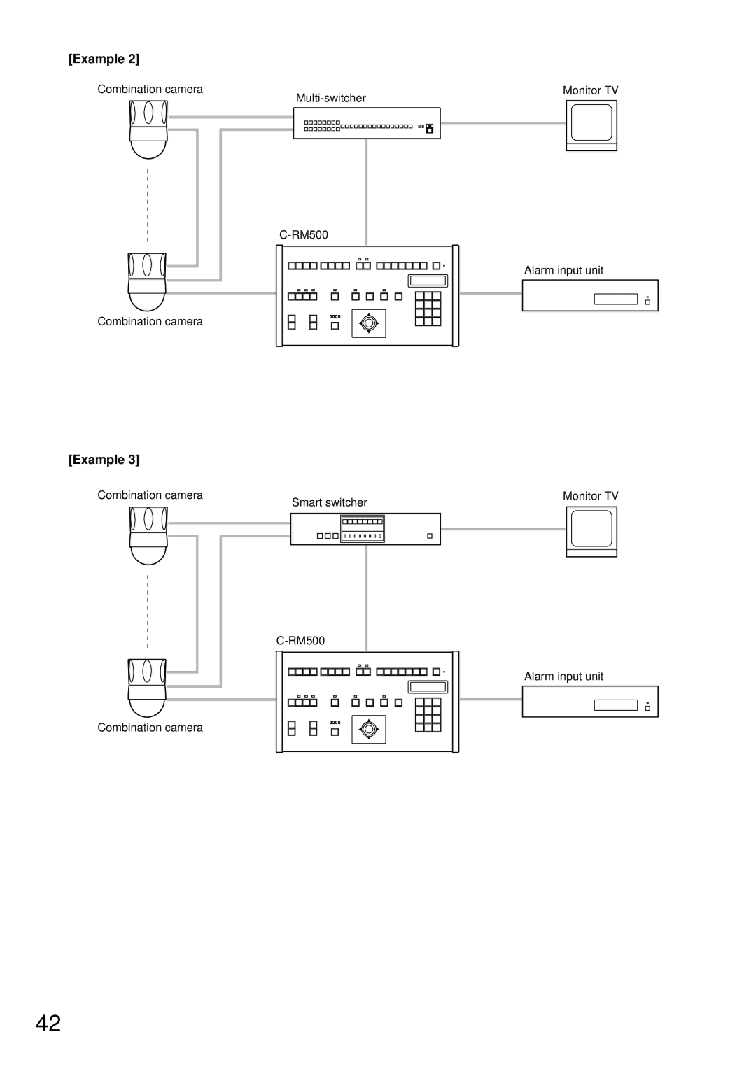
Manuals
/
Brands
/
TV and Video
/
Universal Remote
/
TOA Electronics
/
TV and Video
/
Universal Remote
TOA Electronics
C-RM500
[Example 3], [Example 2]
1
42
52
52
Download
52 pages, 450.4 Kb
42
[Example 3]
Monitor TV
Smart switcher
Combination camera
Combination camera
Alarm input unit
C-RM500
[Example 2]
Monitor TV
Multi-switcher
Combination camera
Combination camera
Alarm input unit
C-RM500
Contents
Main
OPERATING INSTRUCTIONS
REMOTE CONTROLLER C-RM500
1 2 3 4 5 6 7 8 9 C0SET
TABLE OF CONTENTS
1. SAFETY PRECAUTIONS 2. GENERAL DESCRIPTION 3. FUNCTIONS 4. NOMENClATURE AND FUNCTIONS
5. OPERATION
6. SETTINGS
7. CONNECTIONS
8. SPECIFICATIONS
1. SAFETY PRECAUTIONS
WARNING
CAUTION
2. GENERAL DESCRIPTION
3. FUNCTIONS
About the Descriptions in This Manual
Equipment Which Can Be Controlled with the C-RM500
About the Camera Control Terminal
4. NOMENCLATURE AND FUNCTIONS
[Top]
20
1 2 3 4 5 6 7 8 9 10
21 22 23 24 25 26 27 28 29
Page
30 31 32 33 34 35 36 37 38
39
[Rear]
[Bottom]
5. OPERATION
5.1. Operating the Camera
13 CONTROL
13 CHANNEL
DEFROSTER
WIPER
AUX I L IAR Y SW
AUTO
AUTO FOCUS
5POSITION
5.2. Monitor Display
CHA N N E L C A L L
13 FREEZE
DFUNCT I ON KEY 01
25 SET 01
13 CHANNEL 13
16SEGMENT
10SEGMENT
9SEGMENT
4SEGMENT
SEQUENCE
4SEG SEQ
5.3. Alarm Hold and Reset
ALARM HOLD
6. SETTINGS
6.1. Setting Items and Their Descriptions
Joystick
Clear key
SET key
OPERAT I ON MODE 1.MASTER
Setting item Setting content
6.2. Operating Keys and Display Screen
[Keys to be used in setting operations]
6.3. Basic Setting Operations
1234
1.ON 10S EC
6.4. Setting the Functions
1.MASTER
SWI TCH E R 7.SMART 1
SWI TCH E R 1.16INPUT
CONTAC T 1.SELECT CH
Page
HOME POS CH
HOME POS
1TRACE2OFF
1TRACE2POS1
1POS1 2 POS1
I/O SPEED
I/O SPEED CAMERA
19200
38400
BUZZ ER
INITIAL SCREEN 1.FULL
Page
SENSOR ALARM
CAMERA ALARM
Page
CAM1 AL1 123
CAM7 AL1 123
CAM7 AL5 255
CAM7 AL5 123
ALARM SIGNAL 1.EDGE
ALARM T IME 3.20SEC
ALARM FUNCTI ON 1.SEQ
ALARM HOLD 1.KEY
CAM15 POS
CAM15 POS 123
FUNCT I ON KEY A AUTO PAN
ABBREV I AT I ON
CAM28 POS116
CAM28 POS
CPT10SEC
TOUR SEQ NO
C123 P200 T10SEC
C123 P T10SEC
TOUR SEQYES
CAMERA MENU CH
7. CONNECTIONS
Equipment Which Can Be Controlled with the C-RM500
About the Camera Control Terminal
7.1. System Examples
[Example 3]
[Example 2]
a + b + c 1.2 km
<
7.2. Connection to Combination Cameras
7.3. Connection to the Multi-Switcher's RS-232C Terminal
Multi-switcher
Fixed camera
AB
Monitor TV
*
C-RM500
7.4. Connection to the Smart Switcher's RS-232C Terminal
Smart switcher
Fixed camera
Monitor TV
C-RM500
Alarm input unit C-AL80
7.5. Connection When Controlling the System from 2 Locations
7.6. Alarm Output/Control Input Terminal Connections
Page
8. SPECIFICATIONS