Chapter 6 Status indicators for operation and communication
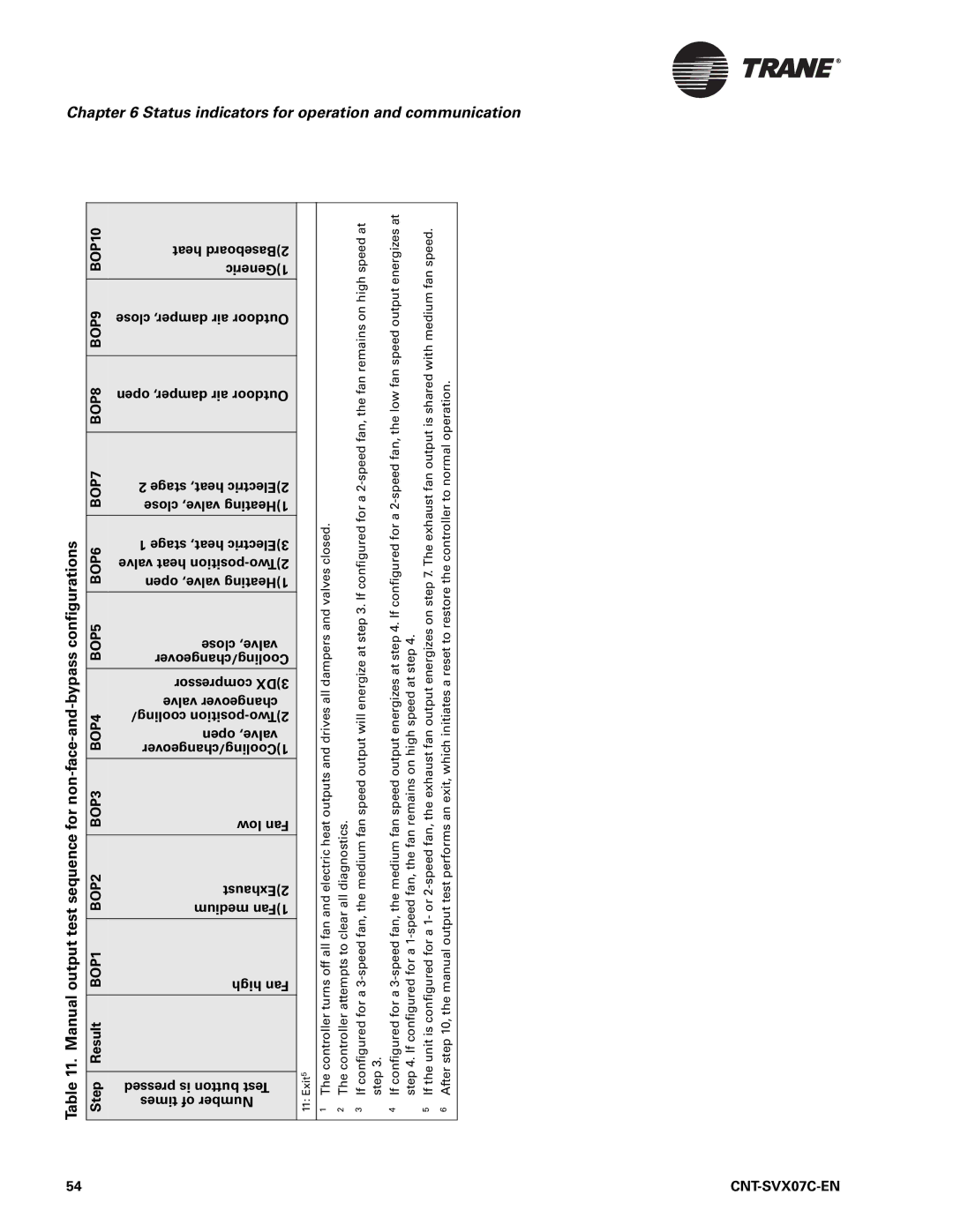
Table 11. Manual output test sequence for
Step Result BOP1 BOP2 BOP3 BOP4 BOP5 BOP6 BOP7 BOP8 BOP9 BOP10
heat 2)Baseboard 1)Generic
close damper, air Outdoor
open damper, air Outdoor
2 stage heat, 2)Electric close valve, 1)Heating
1 stage heat, 3)Electric valve heat
close valve, Cooling/changeover
compressor 3)DX
valve changeover cooling/
open valve, 1)Cooling/changeover
low Fan
2)Exhaust medium 1)Fan
high Fan
pressed is button Test times of Number
11: Exit5
The controller turns off all fan and electric heat outputs and drives all dampers and valves closed. | The controller attempts to clear all diagnostics. | If configured for a | If configured for a | If the unit is configured for a 1- or | After step 10, the manual output test performs an exit, which initiates a reset to restore the controller to normal operation. |
1 | 2 | 3 | 4 | 5 | 6 |
54 |
|
