Vulcan-Hart C24EA3 480V BASIC service manual Water Level Control Components, Water Level Controls

Models: C24EA5 208/240V BASIC C24EA3 480V BASIC C24EA5 208/240V PRO C24EA3 480V PRO C24EA3 208/240V BASIC C24EA3 208/240V PRO C24EA5 480V PRO C24EA5 480V BASIC

1 52
Download 52 pages 5.36 Kb
Page 22
Image 22
WATER LEVEL CONTROL COMPONENTS

MODEL C24EA - WATER LEVEL CONTROL COMPONENTS

WATER LEVEL CONTROL COMPONENTS

WATER LEVEL CONTROLS

Low Level Cut-Off & Differential Control

The steamer is equipped with three water level sensing probes (high, low and low level cut-off) and a water level control board. The water level control board performs two functions: 1) Provide low level cut-off protection to shut off the heat source in case the water level drops below the low level cut-off (LLCO) probe. 2) Perform as a differential level control to maintain the water level between the low and high water level probes.

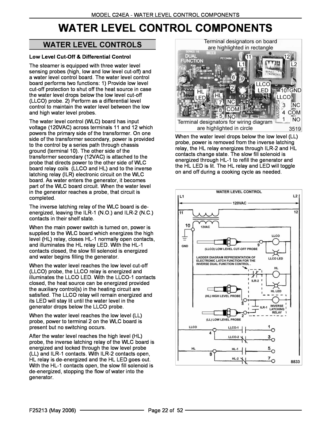
The water level control (WLC) board has input voltage (120VAC) across terminals 11 and 12 which powers the primary side of the transformer. On one side of the transformer secondary, power is provided to the control by a series path through chassis ground (terminal 10). The other side of the transformer secondary (12VAC) is attached to the probe that directs power to the other side of WLC board relay coils (LLCO and HL) and to the inverse latching relay (ILR) electronic circuit on the WLC board. As water enters the generator, it becomes part of the WLC board circuit. When the water level in the generator reaches a probe, that circuit is completed.

The inverse latching relay of the WLC board is de- energized, leaving the ILR-1 (N.O.) and ILR-2 (N.C.) contacts in their shelf state.

When the main power switch is turned on, power is supplied to the WLC board which energizes the high level (HL) relay, closes HL-1 normally open contacts, and illuminates the HL relay LED. With the HL-1 contacts closed, the slow fill solenoid is energized and water begins filling the generator.

When the water level reaches the low level cut-off (LLCO) probe, the LLCO relay is energized and illuminates the LLCO LED. With the LLCO-1 contacts closed, the heat source can be energized provided the auxiliary control(s) in the heating circuit are satisfied. The LLCO relay will remain energized and its LED will stay lit until the water level in the generator drops below the LLCO probe.

When the water level reaches the low level (LL) probe, power to terminal 2 on the WLC board is present but no switching occurs.

After the water level reaches the high level (HL) probe, the inverse latching relay of the WLC board is energized and locked through the low level probe

(LL)and ILR-1 contacts. With ILR-2 contacts open, HL relay is de-energized and the HL LED goes out. With the HL-1 contacts open, the slow fill solenoid is de-energized, stopping the flow of water into the generator.

When the water level drops below the low level (LL) probe, power is removed from the inverse latching relay, the HL relay energizes through ILR-2 and HL contacts change state. The slow fill solenoid is energized through HL-1 to refill the generator and the HL LED is lit. The HL relay and LED will toggle on and off during a cooking cycle as needed.

F25213 (May 2006)


Page 22 of 52


Page 22
Image 22
Vulcan-Hart C24EA3 480V BASIC, C24EA5 480V BASIC, C24EA5 480V PRO Water Level Control Components, Water Level Controls