MODEL C24EA - WATER LEVEL CONTROL COMPONENTS
NOTE: Apply pipe thread sealant to plumbing threads before assembly.
7.Reassemble parts removed in reverse order of removal.
8.For Basic model steamers, perform ON/OFF SWITCH ADJUSTMENT as outlined in ON/OFF SWITCH.
9.Check steamer for leaks and proper operation.
MOTORIZED DRAIN VALVE
(PROFESSIONAL)
WARNING: DISCONNECT THE
ELECTRICAL POWER TO THE
MACHINE AND FOLLOW LOCKOUT /
TAGOUT PROCEDURES.
1.Turn steamer off by using the on/off switch on the front panel of steamer.
A.Allow steamer to complete drain cycle.
B.If motorized drain valve has malfunctioned such that tank will not drain normally, refer to Drain Tank Manually for draining procedure.
Drain Tank Manually
1.Turn off water supply to steamer.
2.Disconnect power to steamer allowing time for water in steam generator tank to cool to 140EF before attempting to manually open drain valve.
3.Remove the RIGHT SIDE PANEL as outlined in COVERS AND PANELS. Rear panel can also be removed for added accessibility.
4.Locate the motorized drain valve found at lower right side of steam generator tank.
5.Push in on the manual drain override knob to disengage the gear set.
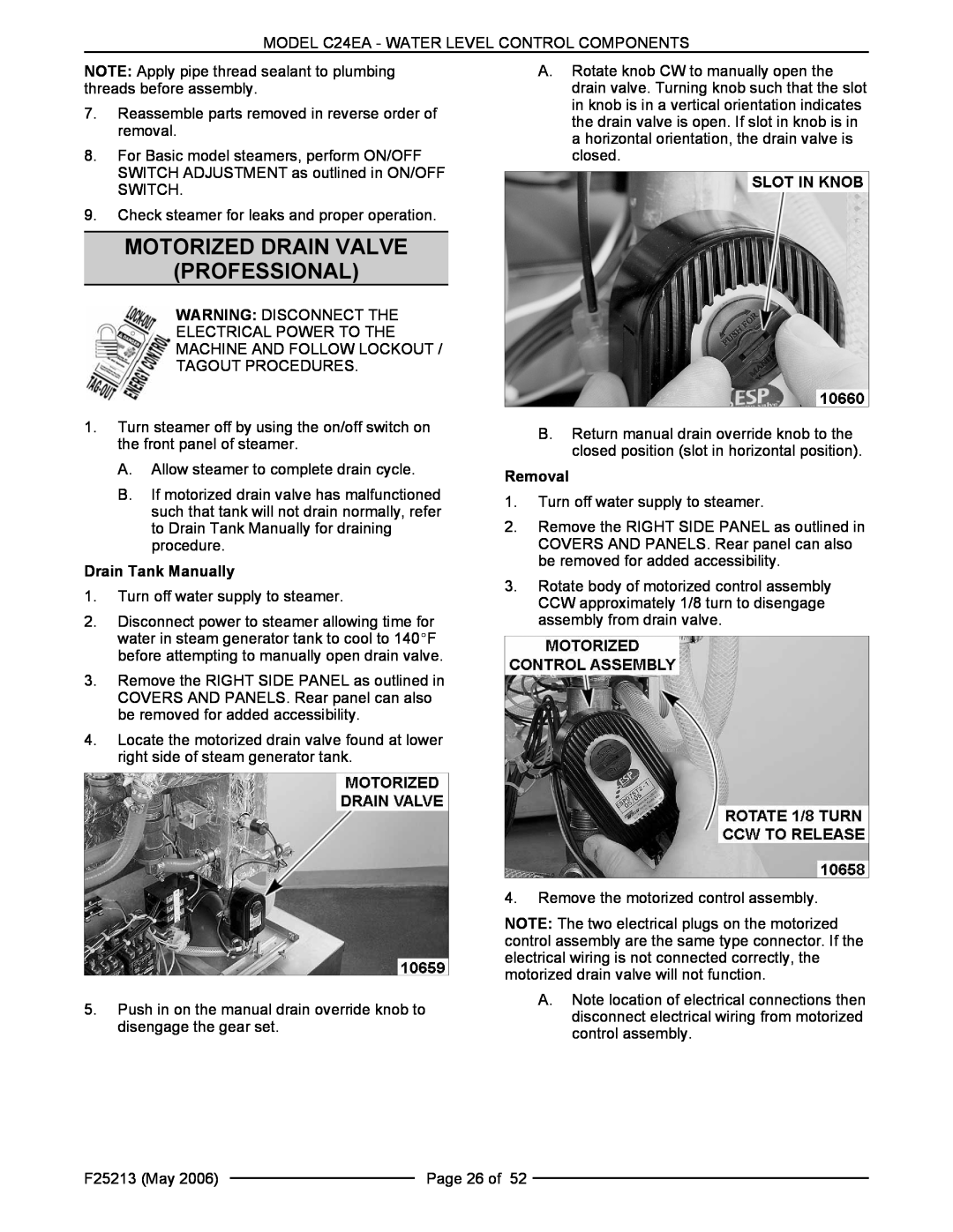
A.Rotate knob CW to manually open the drain valve. Turning knob such that the slot in knob is in a vertical orientation indicates the drain valve is open. If slot in knob is in a horizontal orientation, the drain valve is closed.
B.Return manual drain override knob to the closed position (slot in horizontal position).
Removal
1.Turn off water supply to steamer.
2.Remove the RIGHT SIDE PANEL as outlined in COVERS AND PANELS. Rear panel can also be removed for added accessibility.
3.Rotate body of motorized control assembly CCW approximately 1/8 turn to disengage assembly from drain valve.
4.Remove the motorized control assembly.
NOTE: The two electrical plugs on the motorized control assembly are the same type connector. If the electrical wiring is not connected correctly, the motorized drain valve will not function.
A.Note location of electrical connections then disconnect electrical wiring from motorized control assembly.
F25213 (May 2006) |
| Page 26 of 52 |
|