User Guide | UltraLine Home DSL Router (Models 7400, 7401) |
5. HARDWARE FEATURES
5.1 LED Indicators
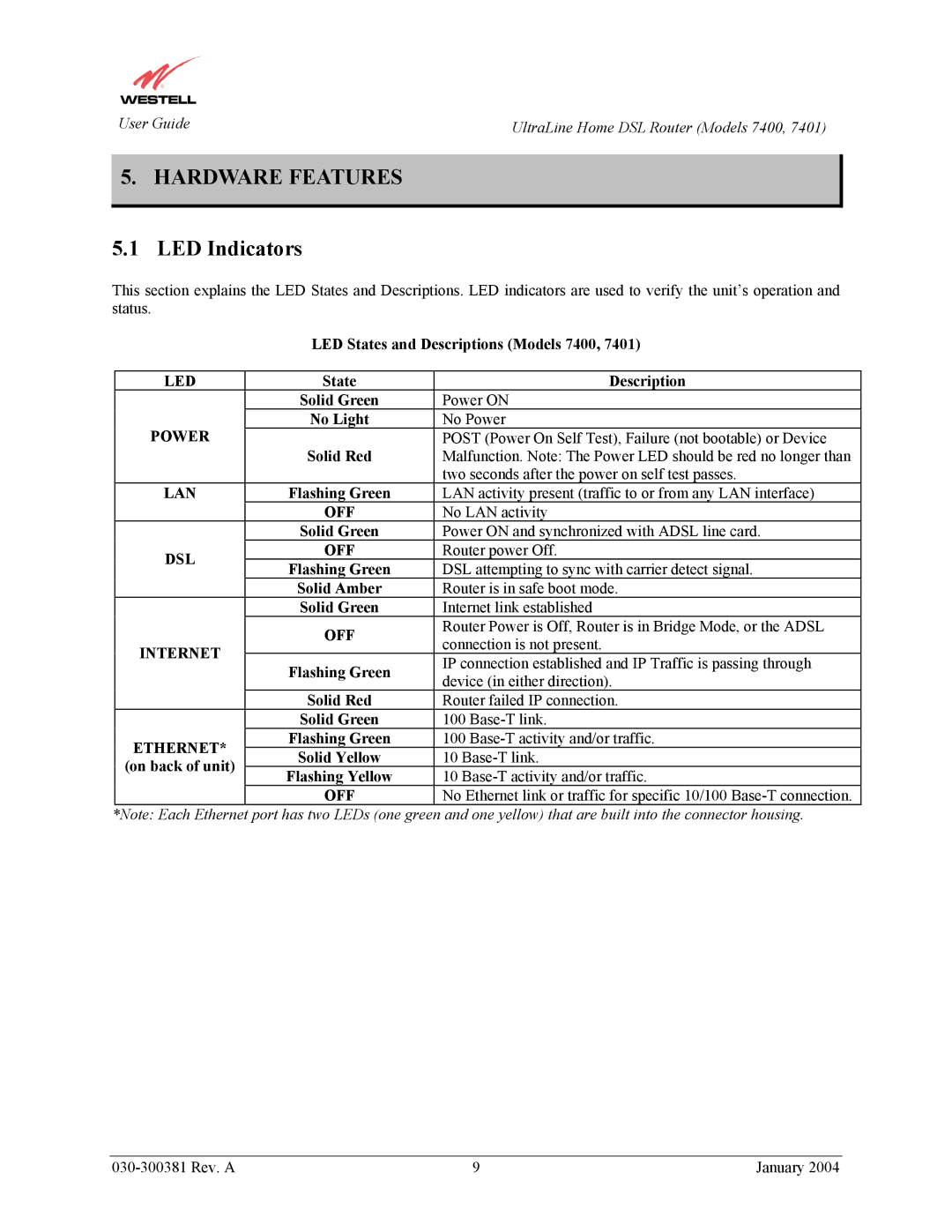
This section explains the LED States and Descriptions. LED indicators are used to verify the unit’s operation and status.
LED States and Descriptions (Models 7400, 7401)
LED | State | Description | |
| Solid Green | Power ON | |
POWER | No Light | No Power | |
Solid Red | POST (Power On Self Test), Failure (not bootable) or Device | ||
| Malfunction. Note: The Power LED should be red no longer than | ||
|
| two seconds after the power on self test passes. | |
LAN | Flashing Green | LAN activity present (traffic to or from any LAN interface) | |
| OFF | No LAN activity | |
| Solid Green | Power ON and synchronized with ADSL line card. | |
DSL | OFF | Router power Off. | |
Flashing Green | DSL attempting to sync with carrier detect signal. | ||
| |||
| Solid Amber | Router is in safe boot mode. | |
| Solid Green | Internet link established | |
| OFF | Router Power is Off, Router is in Bridge Mode, or the ADSL | |
INTERNET | connection is not present. | ||
| |||
Flashing Green | IP connection established and IP Traffic is passing through | ||
| |||
| device (in either direction). | ||
|
| ||
| Solid Red | Router failed IP connection. | |
| Solid Green | 100 | |
ETHERNET* | Flashing Green | 100 | |
Solid Yellow | 10 | ||
(on back of unit) | |||
Flashing Yellow | 10 | ||
| |||
| OFF | No Ethernet link or traffic for specific 10/100 |
*Note: Each Ethernet port has two LEDs (one green and one yellow) that are built into the connector housing.
9 | January 2004 |
