Xantrex Technology PV100S-480 Electrical Diagrams and Schematics, CAUTION Equipment Damage

Models: PV100S-480

1 90
Download 90 pages 29.08 Kb
Page 39
Image 39
Electrical Diagrams and Schematics

Electrical Diagrams and Schematics

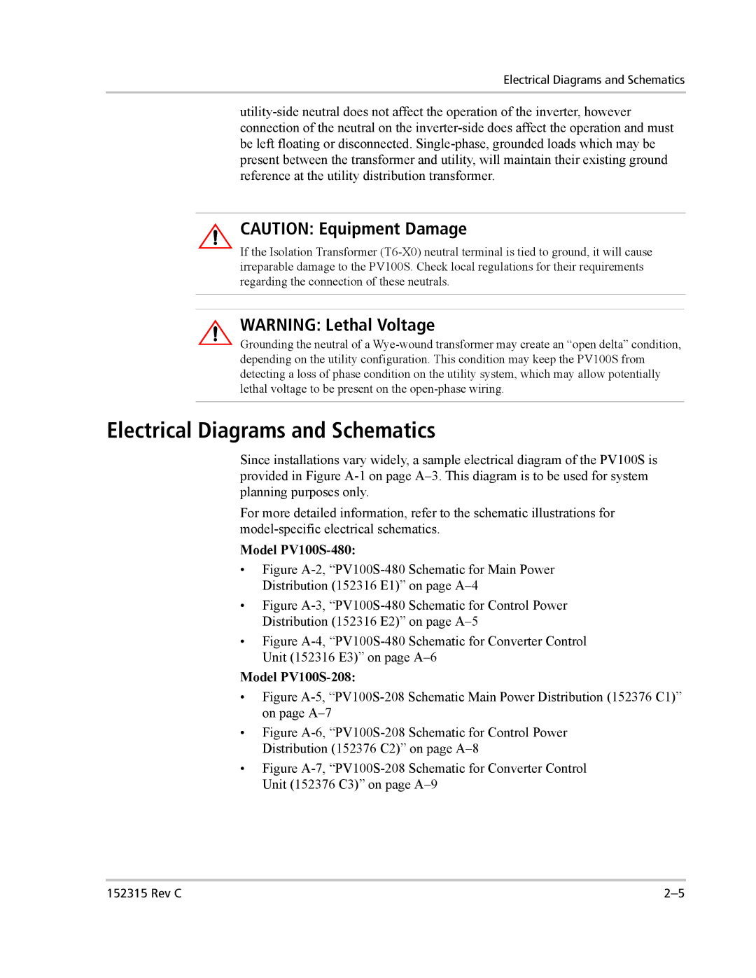
utility-side neutral does not affect the operation of the inverter, however connection of the neutral on the inverter-side does affect the operation and must be left floating or disconnected. Single-phase, grounded loads which may be present between the transformer and utility, will maintain their existing ground reference at the utility distribution transformer.

CAUTION: Equipment Damage

If the Isolation Transformer (T6-X0) neutral terminal is tied to ground, it will cause irreparable damage to the PV100S. Check local regulations for their requirements regarding the connection of these neutrals.

WARNING: Lethal Voltage

Grounding the neutral of a Wye-wound transformer may create an “open delta” condition, depending on the utility configuration. This condition may keep the PV100S from detecting a loss of phase condition on the utility system, which may allow potentially lethal voltage to be present on the open-phase wiring.

Electrical Diagrams and Schematics

Since installations vary widely, a sample electrical diagram of the PV100S is provided in Figure A-1 on page A–3. This diagram is to be used for system planning purposes only.

For more detailed information, refer to the schematic illustrations for model-specific electrical schematics.

Model PV100S-480:

Figure A-2, “PV100S-480 Schematic for Main Power Distribution (152316 E1)” on page A–4

Figure A-3, “PV100S-480 Schematic for Control Power Distribution (152316 E2)” on page A–5

Figure A-4, “PV100S-480 Schematic for Converter Control Unit (152316 E3)” on page A–6

Model PV100S-208:

Figure A-5, “PV100S-208 Schematic Main Power Distribution (152376 C1)” on page A–7

Figure A-6, “PV100S-208 Schematic for Control Power Distribution (152376 C2)” on page A–8

Figure A-7, “PV100S-208 Schematic for Converter Control Unit (152376 C3)” on page A–9

152315 Rev C

2–5

Page 39
Image 39
Xantrex Technology PV100S-480 Electrical Diagrams and Schematics, CAUTION Equipment Damage, WARNING Lethal Voltage