| Wiring - General |
| |
Chassis Ground | The chassis ground is a copper bus bar in the Main Inverter Enclosure and has |
| 3/8-16" bolts for terminating the AC ground. The ground conductor size depends |
| on the size of the main circuit breaker. |
| NEC Table 250.122 (Ninth Edition) requires that the ground conductor be at least |
| #3 AWG for a 400 A circuit breaker and #6 AWG for a 200 A circuit breaker. |
Torque connections to ground bar in the Main Inverter Enclosure as follows:
•PV100S-208 - 420 in-lbs (47.5 Nm)
•PV100S-480 - 420 in-lbs (47.5 Nm)
The equipment ground on the PV100S is marked with this symbol: 
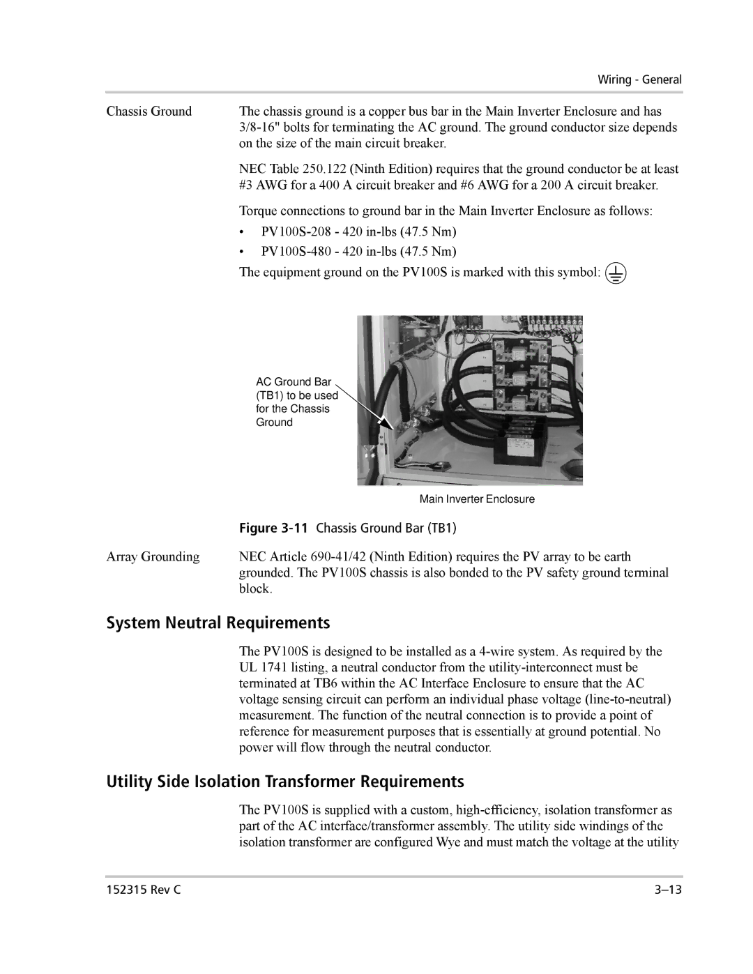
AC Ground Bar (TB1) to be used for the Chassis Ground
| Main Inverter Enclosure |
| Figure 3-11Chassis Ground Bar (TB1) |
Array Grounding | NEC Article 690-41/42 (Ninth Edition) requires the PV array to be earth |
| grounded. The PV100S chassis is also bonded to the PV safety ground terminal |
| block. |
System Neutral Requirements
The PV100S is designed to be installed as a 4-wire system. As required by the UL 1741 listing, a neutral conductor from the utility-interconnect must be terminated at TB6 within the AC Interface Enclosure to ensure that the AC voltage sensing circuit can perform an individual phase voltage (line-to-neutral) measurement. The function of the neutral connection is to provide a point of reference for measurement purposes that is essentially at ground potential. No power will flow through the neutral conductor.
Utility Side Isolation Transformer Requirements
The PV100S is supplied with a custom, high-efficiency, isolation transformer as part of the AC interface/transformer assembly. The utility side windings of the isolation transformer are configured Wye and must match the voltage at the utility