Installation
Wire Gauge and Torque Requirements
Table
Table 3-1 AC Terminal Wire Gauge, Bolt Size, and Torque Values
AC Terminal | Acceptable Wire Size | Bolt (Hardware) Size | Torque Requirements | ||
|
|
|
| ||
Connections | Range (both models) | ||||
|
|
|
|
|
|
TB1 | 500MCM to #4 AWG | 420 | 420 | ||
(Chassis Ground) | (1 stud per pole) |
|
| (47.5 Nm) | (47.5 Nm) |
|
|
|
|
|
|
TB2 | 500MCM to #4 AWG | 420 | 420 | ||
(System Ground) | (1 stud per pole) |
|
| (47.5 Nm) | (47.5 Nm) |
|
|
|
|
|
|
TB6 (Neutral) | 500MCM to #4 AWG | 228 | 228 | ||
| (1 stud per pole) |
|
| (25.7 Nm) | (25.7 Nm) |
|
|
|
|
|
|
350MCM to #6 AWG | M10 (See Caution | M8 (See Caution | 310 | 115 | |
(1 stud per pole) | on page | on page | (35.0 Nm) | (13.0 Nm) | |
|
|
|
|
|
|
350MCM to #6 AWG | 420 | 420 | |||
(1 stud per pole) |
|
| (47.5 Nm) | (47.5 Nm) | |
|
|
|
|
|
|
350MCM to #4 AWG | 5/16 Hex | 5/16 Hex | 275 | 275 | |
(2 openings per pole) |
|
| (31 Nm) | (31 Nm) | |
|
|
|
|
|
|
Table
Table 3-2 DC Terminal Wire Gauge, Bolt Size, and Torque Values
DC Terminal | Acceptable Wire Size | Bolt (Hardware) Size | Torque Requirements | ||
|
|
|
| ||
Connections | Range (both models) | ||||
|
|
|
|
|
|
500MCM to #4 AWG | 7/16 Hex | 7/16 Hex | 500 | 500 | |
(2 openings per pole) |
|
| (56.5 Nm) | (56.5 Nm) | |
|
|
|
|
|
|
Grounding
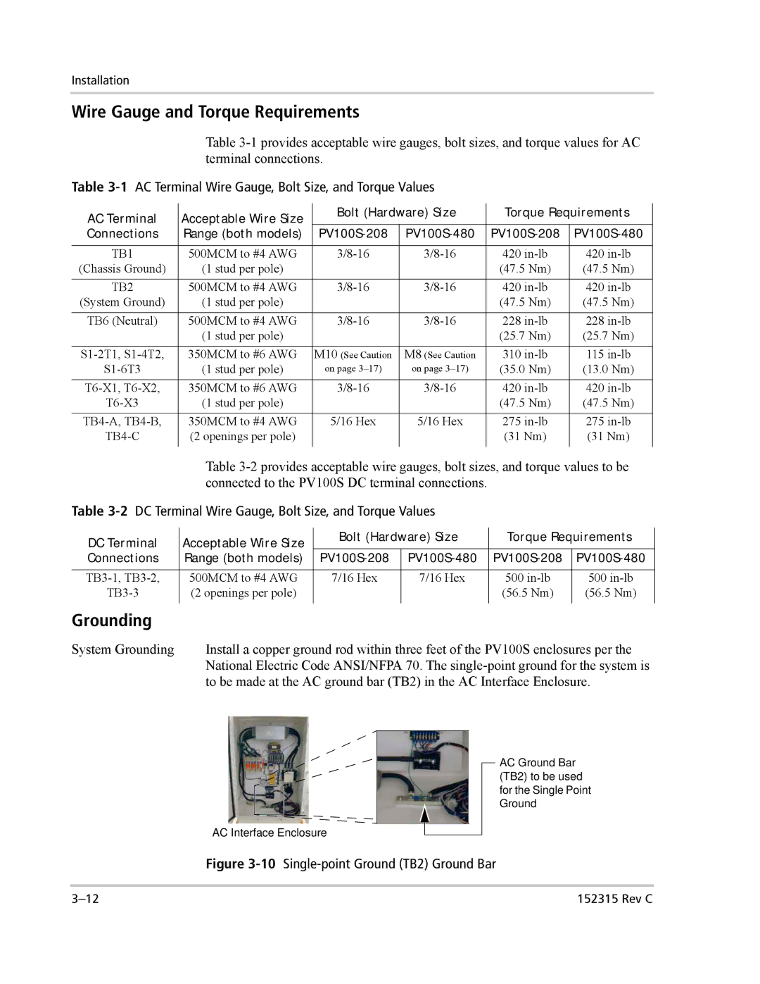
System Grounding | Install a copper ground rod within three feet of the PV100S enclosures per the |
| National Electric Code ANSI/NFPA 70. The |
| to be made at the AC ground bar (TB2) in the AC Interface Enclosure. |
AC Interface Enclosure
AC Ground Bar (TB2) to be used for the Single Point Ground
Figure 3-10 Single-point Ground (TB2) Ground Bar
152315 Rev C |