Planning
Conduit Penetration
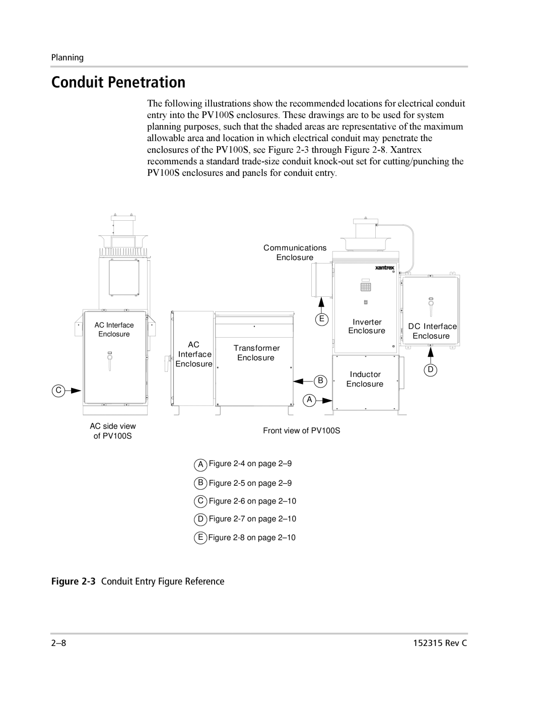
The following illustrations show the recommended locations for electrical conduit entry into the PV100S enclosures. These drawings are to be used for system planning purposes, such that the shaded areas are representative of the maximum allowable area and location in which electrical conduit may penetrate the enclosures of the PV100S, see Figure
Communications
Enclosure
AC Interface
Enclosure
C ![]()
![]()
AC side view
of PV100S
AC
Interface
Enclosure
E | Inverter |
| Enclosure |
Transformer
Enclosure
Inductor
B Enclosure
A ![]()
![]()
Front view of PV100S
DC Interface Enclosure
D
A Figure 2-4 on page 2–9
B Figure 2-5 on page 2–9
C Figure 2-6 on page 2–10
D Figure 2-7 on page 2–10
 Figure
 2-8 on page 2–10
Figure 2-3 Conduit Entry Figure Reference
152315 Rev C |