Wiring - Specific
PV Array Connections
To make the connections from the PV Array/combiner to DC Interface enclosure:
1.Remove the door clamps and open the door to the DC Interface Enclosure.
2.Route the PV Array cables conductors POSitive (PV+), NEGative
3.The DC power conductor terminations are made at the
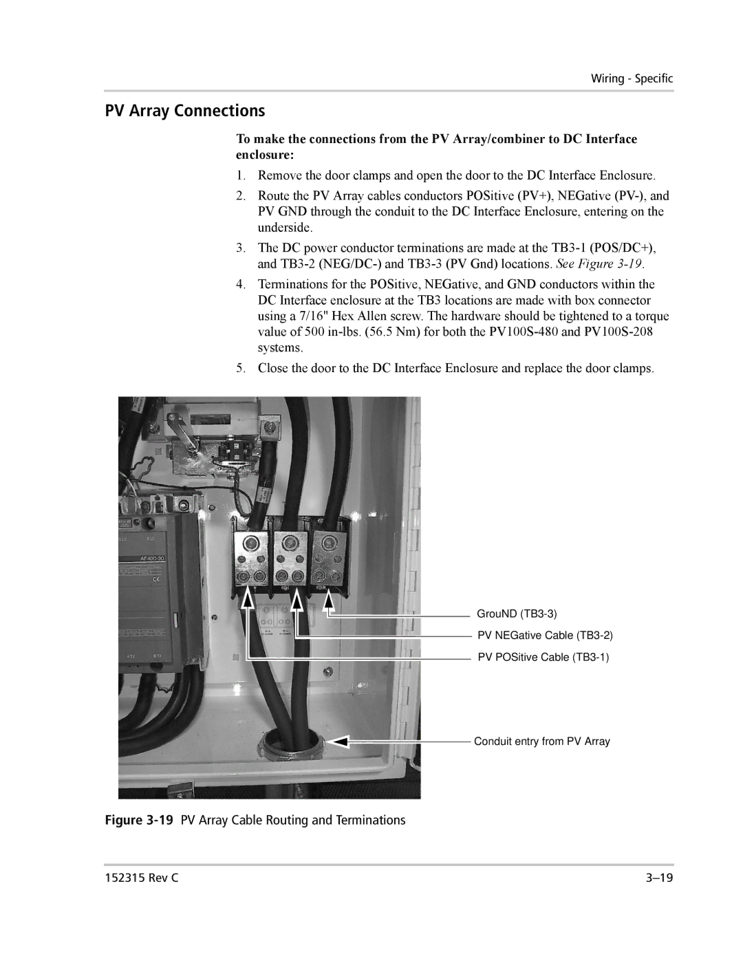
4.Terminations for the POSitive, NEGative, and GND conductors within the DC Interface enclosure at the TB3 locations are made with box connector using a 7/16" Hex Allen screw. The hardware should be tightened to a torque value of 500
5.Close the door to the DC Interface Enclosure and replace the door clamps.
GrouND
PV NEGative Cable
PV POSitive Cable
Conduit entry from PV Array
Figure 3-19 PV Array Cable Routing and Terminations
152315 Rev C |