Wiring - Specific
3.In addition to the power conductors, route the AC Sense Harness assembly (Xantrex P/N
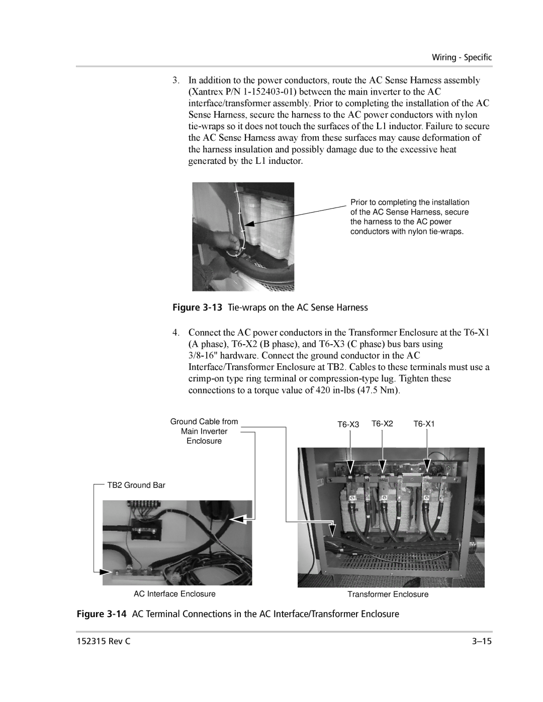
Prior to completing the installation of the AC Sense Harness, secure the harness to the AC power conductors with nylon
Figure 3-13 Tie-wraps on the AC Sense Harness
4.Connect the AC power conductors in the Transformer Enclosure at the
Ground Cable from
Main Inverter
Enclosure
![]() TB2 Ground Bar
TB2 Ground Bar
AC Interface Enclosure | Transformer Enclosure |
Figure 3-14 AC Terminal Connections in the AC Interface/Transformer Enclosure
152315 Rev C |