Xantrex Technology PV100S-480 installation manual 18 AC Terminal Connections from the Utility

Models: PV100S-480

1 90
Download 90 pages 29.08 Kb
Page 66
Image 66
S1-2T1

Installation

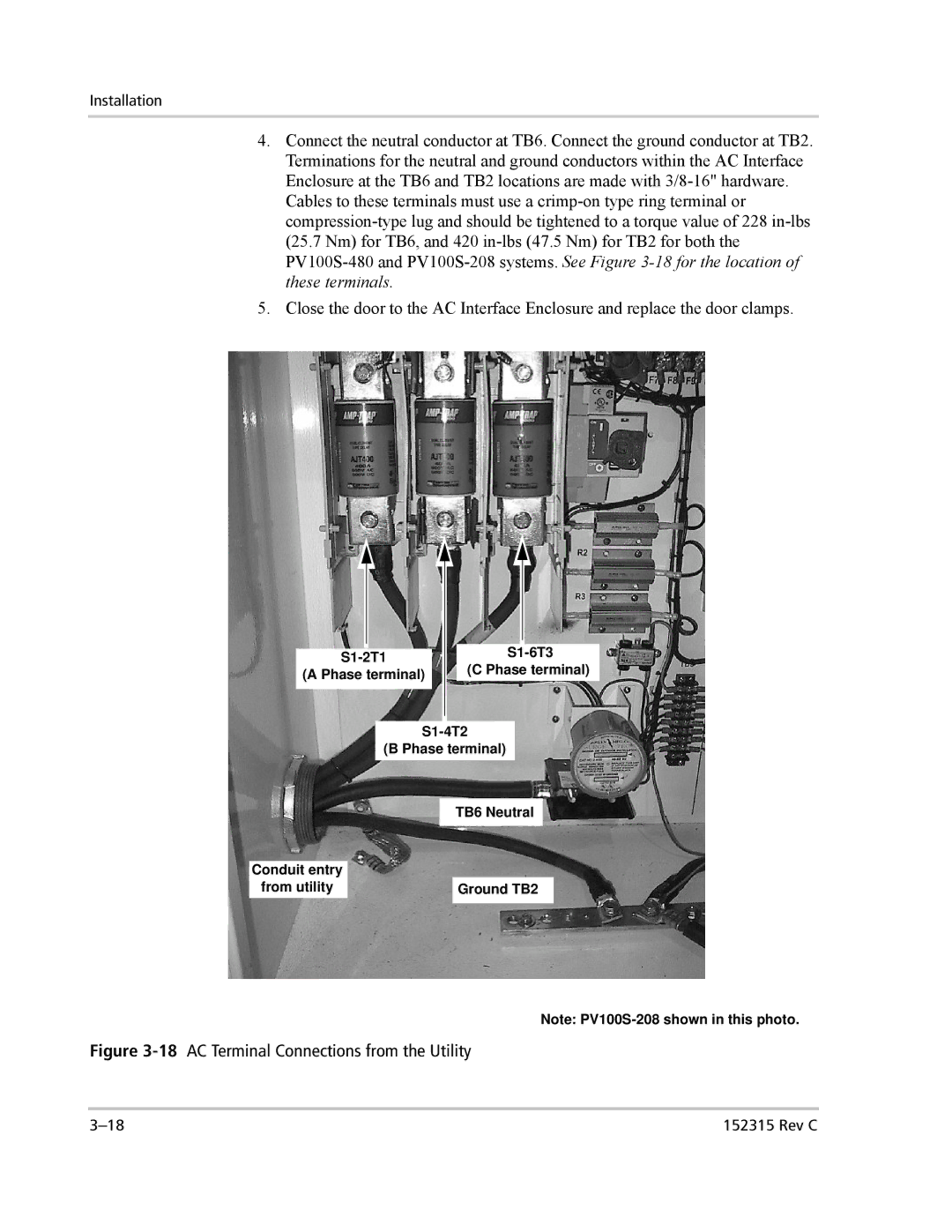
4.Connect the neutral conductor at TB6. Connect the ground conductor at TB2. Terminations for the neutral and ground conductors within the AC Interface Enclosure at the TB6 and TB2 locations are made with 3/8-16" hardware. Cables to these terminals must use a crimp-on type ring terminal or compression-type lug and should be tightened to a torque value of 228 in-lbs (25.7 Nm) for TB6, and 420 in-lbs (47.5 Nm) for TB2 for both the PV100S-480 and PV100S-208 systems. See Figure 3-18 for the location of these terminals.

5.Close the door to the AC Interface Enclosure and replace the door clamps.

S1-2T1

(A Phase terminal)

S1-6T3

(C Phase terminal)

Conduit entry

from utility

S1-4T2

(B Phase terminal)

TB6 Neutral

Ground TB2

Note: PV100S-208 shown in this photo.

Figure 3-18AC Terminal Connections from the Utility

3–18

152315 Rev C

Page 66
Image 66
Xantrex Technology PV100S-480 installation manual 18 AC Terminal Connections from the Utility, S1-2T1 A Phase terminal