Xantrex Technology PV100S-480 15 AC Terminal Connections in the Main Inverter Enclosure, A phase

Models: PV100S-480

1 90
Download 90 pages 29.08 Kb
Page 64
Image 64
Figure 3-15AC Terminal Connections in the Main Inverter Enclosure

Installation

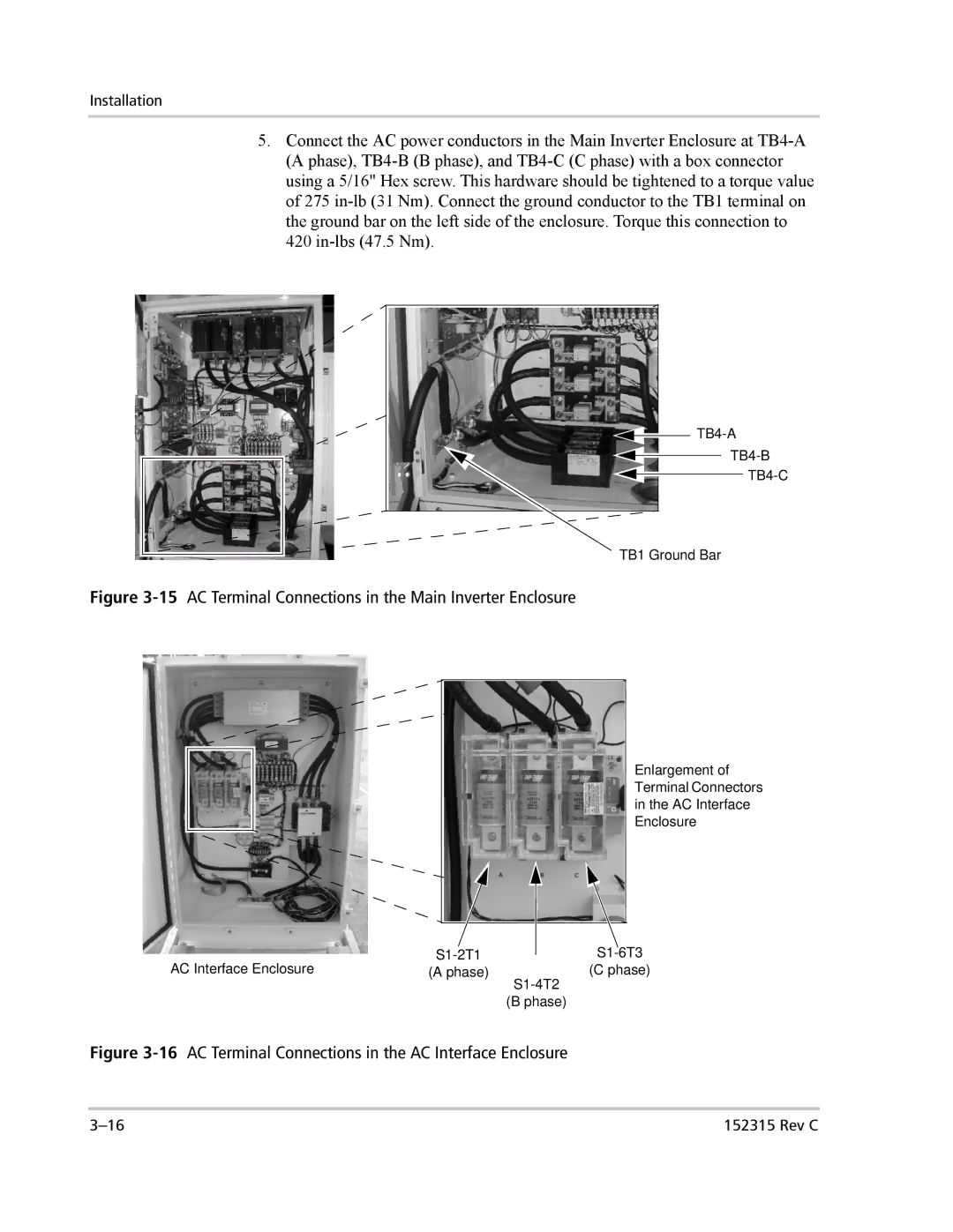
5.Connect the AC power conductors in the Main Inverter Enclosure at TB4-A (A phase), TB4-B (B phase), and TB4-C (C phase) with a box connector using a 5/16" Hex screw. This hardware should be tightened to a torque value of 275 in-lb (31 Nm). Connect the ground conductor to the TB1 terminal on the ground bar on the left side of the enclosure. Torque this connection to 420 in-lbs (47.5 Nm).

TB4-A

TB4-B

TB4-C

TB1 Ground Bar

Figure 3-15AC Terminal Connections in the Main Inverter Enclosure

Enlargement of

Terminal Connectors

in the AC Interface

Enclosure


AC Interface Enclosure

S1-2T1


S1-6T3


(A phase)


(C phase)


S1-4T2


(B phase)

Figure 3-16AC Terminal Connections in the AC Interface Enclosure

3–16

152315 Rev C

Page 64
Image 64
Xantrex Technology PV100S-480 15 AC Terminal Connections in the Main Inverter Enclosure, A phase, C phase, S1-4T2, B phase