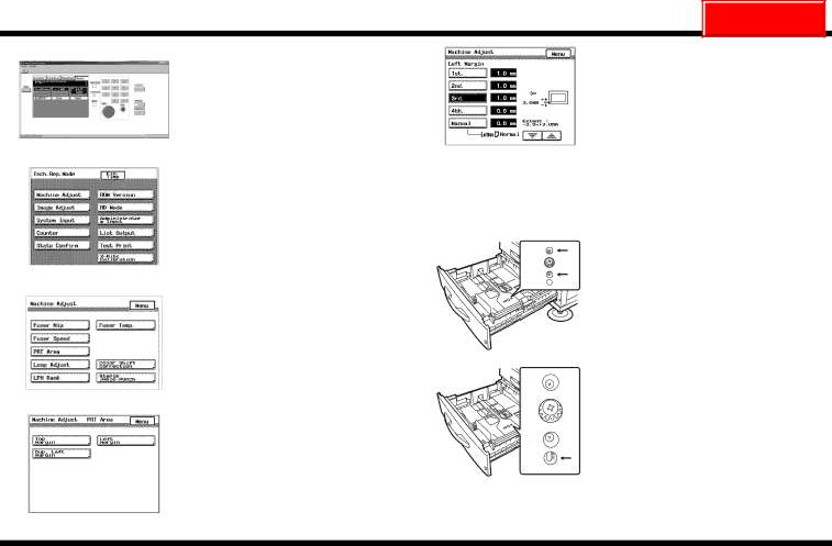
Cisco Systems CF2001P user manual Adjusting the Paper Reference Position for PF-118

Page 32

CF2001P

NEXT

Adjusting the Paper Reference Position for PF-118

1.Check that the External Panel Controller appears in the computer screen, and then display the Tech. Rep. Mode screen. (For details about displaying the Tech. Rep. Mode screen, refer to the Service Manual.)

C4004P565CA

2. Click [Machine Adjust].

5.Select the paper drawer that you wish to adjust, and then click the up and down arrows in the lower-right corner of the screen to enter the difference between the mea- sured width and the standard width.

6.Print a test page and check the paper refer- ence position.


If the width of the measure margin does not

C4658O005CA


meet its standard width, follow the instruc-


tions described below.

7.Open the paper drawer for the cassette that needs to be adjusted, and then remove all of the paper.

C4004P597CA

3. Click [PRT Area].

C4658U024AA

8.Loosen the two screws on the guide plate at the bottom of the paper drawer.

C4004P588CA

4. Click [Left Margin].

9. Adjust the guide plate to the appropriate

position on the scale inside the paper

drawer.

C4658U025AA

C4658P003CA

4004-7715-01

– 31 –


Image 32
Contents CF2001P Outline of the CF2001P System Setup Unpacking the Printer Unpacking the AccessoriesUnpacking Removing the Protective Tape and Packing Materials Installing the Units Installing the Imaging UnitsClear plastic protective sheet is not Packing material therefore, do not removeShaded area, is only attached to Black imaging unitInstalling the Oil-Coating Unit Be sure to install the imaging units in their correct slotsBe sure to support the upper right-side door While carefully opening it otherwise, it mayRemove the oil-coating unit from its box Filling the Toner C4004U062AA Affixing the Support Label Connecting the CablesAffix the label that corresponds with the installed options Loading Test Paper Installing the Manual HolderChecking the Operation of the Printer Setting Up the Servicing Equipment CF2001PSetting Up the Converter Setting Up the Selector Connecting the Equipment Cables TorRite Caliblation Click X-Rite Calibration in the Tech. Rep. Mode screen Dialog box appears if the auto-cal strip was read correctly Turn the cyan test pattern to its original ori Dialog box If the cyan test pattern is read correctlyRead the Pattern of Cyan disappears from Making System Setting Checking the Date SettingSpecifying the Serial Number Specifying Who Performs Replacements Printing the List Click Image Processing To set the Energy Save Mode parameter Select the C Clear key to erase the entered numberTo set the Sleep Mode parameter Loading Paper TraySlide the lateral guides against the edges Paper Adjusting the Options Checking the Paper Reference Position for PF-118Click PRT Area Adjusting the Paper Reference Position for PF-118 Click Machine Adjust Click Left Margin Do not measure from the back of the test PatternChecking the Hole-Punching Positions for FN-107 Setting DT-105 USA and Canada only Connecting the Telephone CablesPrecautions for Connecting a Telephone to the Data Terminal Transmission SettingsDate/Time Settings Enter the service representative’s ID code Maintenance Center Billing Center SettingsClearing the Maintenance RAM DT Settings If the number is not 6-digits long, add 0 at the beginningSetting the Telephone Number Return Initial Transmission