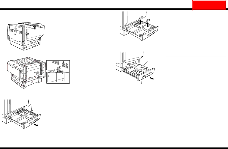
Cisco Systems CF2001P user manual Removing the Protective Tape and Packing Materials

Page 4

CF2001P

NEXT

Removing the Protective Tape and Packing Materials

<Outside Surface of the Printer>

Remove the tape affixed to the outside sur- face of the printer.

C4004U145AA

C4004U005AA

Paper take-up roller

Packing material

Tapes C4004U026AB

C4004U006AA

3.Remove the 2 pieces of packing material from the paper-lifting plate.

4.Close the paper drawer.

5.Pull out the paper drawer for Tray 2.

NOTE

Be careful not to touch the surface of the paper take-up roller with your hands. If the roller has been touched, wipe it with a dry cloth.

6.Remove the 3 pieces of tape affixed to the paper-lifting plate as shown.

<Paper Feed Section>

Packing material

Paper take-up roller

1. Pull out the paper drawer for Tray 1.

NOTE

Be careful not to touch the surface of the paper take-up roller with your hands. If the roller has been touched, wipe it with a dry cloth.

7.Remove the packing material from the paper-lifting plate.

8 Close the paper drawer.

C4004U024AA

2.Remove the 2 pieces of tape shown in the illustration from the paper-lifting plate.

4004-7715-01

– 3 –


Image 4
Contents CF2001P Outline of the CF2001P System Setup Unpacking Unpacking the AccessoriesUnpacking the Printer Removing the Protective Tape and Packing Materials Installing the Units Installing the Imaging UnitsClear plastic protective sheet is not Packing material therefore, do not removeShaded area, is only attached to Black imaging unitInstalling the Oil-Coating Unit Be sure to install the imaging units in their correct slotsBe sure to support the upper right-side door While carefully opening it otherwise, it mayRemove the oil-coating unit from its box Filling the Toner C4004U062AA Affix the label that corresponds with the installed options Connecting the CablesAffixing the Support Label Checking the Operation of the Printer Installing the Manual HolderLoading Test Paper Setting Up the Servicing Equipment CF2001PSetting Up the Converter Setting Up the Selector Connecting the Equipment Cables TorRite Caliblation Click X-Rite Calibration in the Tech. Rep. Mode screen Dialog box appears if the auto-cal strip was read correctly Turn the cyan test pattern to its original ori Read the Pattern of Cyan disappears from If the cyan test pattern is read correctlyDialog box Making System Setting Checking the Date SettingSpecifying the Serial Number Specifying Who Performs Replacements Printing the List Click Image Processing To set the Energy Save Mode parameter Select the C Clear key to erase the entered numberTo set the Sleep Mode parameter Loading Paper TraySlide the lateral guides against the edges Paper Adjusting the Options Checking the Paper Reference Position for PF-118Click PRT Area Adjusting the Paper Reference Position for PF-118 Click Machine Adjust Click Left Margin Do not measure from the back of the test PatternChecking the Hole-Punching Positions for FN-107 Setting DT-105 USA and Canada only Connecting the Telephone CablesPrecautions for Connecting a Telephone to the Data Terminal Transmission SettingsDate/Time Settings Clearing the Maintenance RAM Maintenance Center Billing Center SettingsEnter the service representative’s ID code DT Settings If the number is not 6-digits long, add 0 at the beginningSetting the Telephone Number Return Initial Transmission