Dell 1600SC manual Removing the Microprocessor Fan and Heat Sink Assembly

Page 73

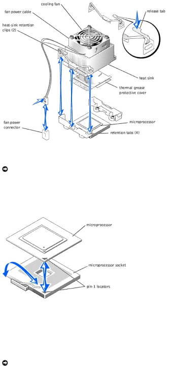
7.Remove the microprocessor fan and heat sink assembly (see Figure 6-5):

a.Press down on the release tabs on the heat-sink retention clips to release the clips from the retaining tabs on the ZIF socket.

b.Lift the assembly away from the microprocessor.

Figure 6-5. Removing the Microprocessor Fan and Heat Sink Assembly

8.Pull the microprocessor socket release lever upward to the fully open position (see Figure 6-6).

NOTICE: Be careful not to bend any of the pins when removing the microprocessor. Bending the pins can permanently damage the microprocessor.

9.Lift the microprocessor out of the socket and leave the release lever in the open position so that the socket is ready for the new microprocessor (see

Figure 6-6).

Figure 6-6. Removing and Installing a Microprocessor

10.Unpack the new microprocessor.

If any of the pins on the microprocessor appear bent, see "Getting Help" for instructions on obtaining technical assistance.

11.Ensure that the microprocessor socket release lever is in the fully open position.

NOTICE: The microprocessor and system board can be damaged if the microprocessor socket release lever is not fully open when you insert the new microprocessor.

12.Align pin 1 on the microprocessor (see Figure 6-6) with pin 1 on the microprocessor socket.

Image 73
Contents Initial release 22 Sep Jumpers-A General Explanation Jumpers, Switches, and ConnectorsSystem Board Jumpers JumpersTable A-1. System Board Jumper Settings System Board ConnectorsJumper Setting Description Table A-2. System Board Connectors Disabling a Forgotten PasswordConnector Description Back to Contents Connectors Ports and ConnectorsTable B-1. I/O Connector Icons Icon ConnectorParallel Connector Serial ConnectorSerial Connector Autoconfiguration Pin Signal DefinitionTable B-3. Parallel Connector Pin Assignments PS/2-Compatible Keyboard and Mouse Connectors18-25 USB Connector Video ConnectorPin Signal I/O Definition Integrated NIC ConnectorNetwork Cable Requirements Abbreviations and Acronyms CGA Dimm EMI GUI LAN MBR Ntfs Pqfp SBE UMB ZIF Other Documents You May Need IntroductionObtaining Technical Assistance Front-Panel Features Indicators, Codes, and MessagesComponent Description Back-Panel FeaturesPower Button Indicators Power Indicator CodesIndicator Function NIC Indicator Codes Hard-Drive Indicator CodesHard-Drive Status Indicator Codes Drive-Status Indicator Indicator CodeIndicator Indicator Code NIC Indicator CodesSystem Messages System MessagesDiskette Drive, Troubleshooting a CD Drive, Troubleshooting Guide System Beep Codes Code Cause Corrective Action System Beep CodesAlert Messages Diagnostics MessagesTroubleshooting Errors and Conflicts Finding Software SolutionsInput Errors Before You BeginApplication Conflicts IRQ Assignment DefaultsIRQ Assignment Conflicts IRQ Line AssignmentRunning Server Administrator Diagnostics Running the System DiagnosticsFeatures of the System Diagnostics When to Use the System DiagnosticsUsing the System Diagnostics Error Messages Using the Device Groups MenuSafety First-For You and Your System Troubleshooting Your SystemChecking Specific System Problems External ConnectionsSystem Orientation Start-Up RoutineStart-Up Routine Indications Look/listen for ActionRemoving the Bezel BezelInstalling the Cover Installing the BezelSystem Cover BaffleTroubleshooting the Video Subsystem Installing the BaffleChecking the Equipment Removing the BaffleTroubleshooting the Mouse Troubleshooting the KeyboardTroubleshooting a Serial I/O Device Troubleshooting the Basic I/O FunctionsTroubleshooting a USB Device Troubleshooting a Parallel PrinterInside the System Troubleshooting a NICResponding to a Systems Management Alert Message Troubleshooting a Wet SystemTroubleshooting the System Battery Troubleshooting a Damaged SystemTroubleshooting Redundant Power Supplies Troubleshooting System Cooling Troubleshooting a Nonredundant Power SupplyTroubleshooting Expansion Cards Troubleshooting System Memory Troubleshooting the Diskette Drive Troubleshooting a CD Drive Troubleshooting an IDE Tape Drive Troubleshooting a Tape DriveTroubleshooting a Scsi Tape Drive Troubleshooting an IDE Hard Drive Troubleshooting Hard DrivesTroubleshooting a Scsi Hard Drive System With Scsi Backplane Troubleshooting an IDE Hard Drive in a RAID ConfigurationHard-drive cables Device drivers Troubleshooting a Microprocessor Troubleshooting a RAID Controller CardTroubleshooting the System Board Resetting Corrupted Bios Configuration Back to Contents System Fans Installing System OptionsRemoving the Front System Fan Installing the Back System Fan Installing the Front System FanRemoving the Back System Fan Removing a Redundant Power Supply Redundant Power SuppliesInstalling a Redundant Power Supply Expansion Cards Installing an Expansion CardRemoving an Expansion Card Removing and Installing an Expansion CardMemory Module Installation Guidelines Memory Upgrade KitsPerforming a Memory Upgrade Sample Memory Module ConfigurationsRemoving and Installing a Memory Module Installing Memory ModulesMicroprocessors Removing and Installing a MicroprocessorRemoving Memory Modules Removing the Microprocessor Fan and Heat Sink Assembly Replacing the System Battery System BatteryReplacing the System Battery Connecting Drives Installing DrivesDrive Cable Configurations DC Power CablesScsi Configuration Information IDE Configuration InformationScsi Interface Cables Scsi ID NumbersInstalling a Diskette Drive Configuring the Boot DriveDiskette Drive Removing a Diskette DriveRemoving the Front-Panel Drive Inserts Front-Panel Drive InsertsInstalling a 5.25-Inch Drive Installing the Front-Panel Drive InsertsInch Drives Page Hard Drives General Installation GuidelinesRemoving and Installing a Non-Hot-Plug Hard Drive Installing and Removing Non-Hot-Plug Hard DrivesInstalling a Non-Hot-Plug Hard Drive Page Installing and Removing Hot-Plug Scsi Hard Drives Removing a Hot-Plug Hard Drive Installing a Hot-Plug Hard Drive Installing a RAID Controller CardBack to Contents Getting Help Online ServicesTechnical Assistance Automated Order-Status Service AutoTech ServiceTechnical Support Service Ftp.dell.comBefore You Call Contacting Dell Diagnostics ChecklistAntigua and Barbuda Argentina Buenos Aires0011 Australia SydneyAustria Vienna Website support.euro.dell.com 900Costa Rica ColombiaCzech Republic Prague Website support.euro.dell.com Denmark Copenhagen Website support.euro.dell.comGreece Website support.euro.dell.com Germany Langen Website support.euro.dell.comGrenada GuatemalaLatin America Korea SeoulLuxembourg Website support.euro.dell.com MacaoNicaragua New ZealandNorway Lysaker Website support.euro.dell.com Panama005 Grenadines Singapore SingaporeSouth Africa Johannesburg Website support.euro.dell.com 09/091Turks and Caicos Islands Trinidad/TobagoBracknell Website support.euro.dell.com Uruguay