Company X Accessories C1030-5510 manual Introduction, Changes to previous versions

Page 30

Software

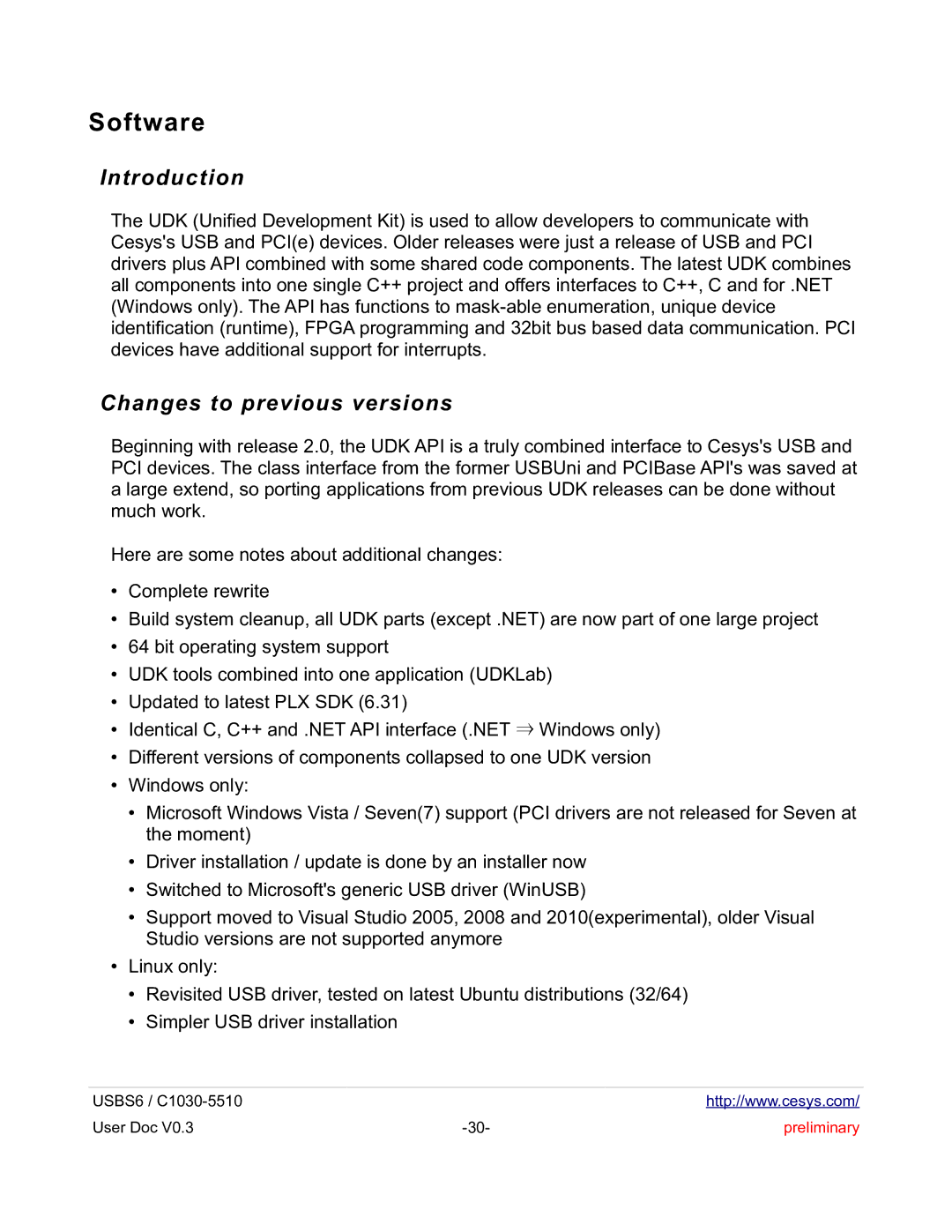
Introduction

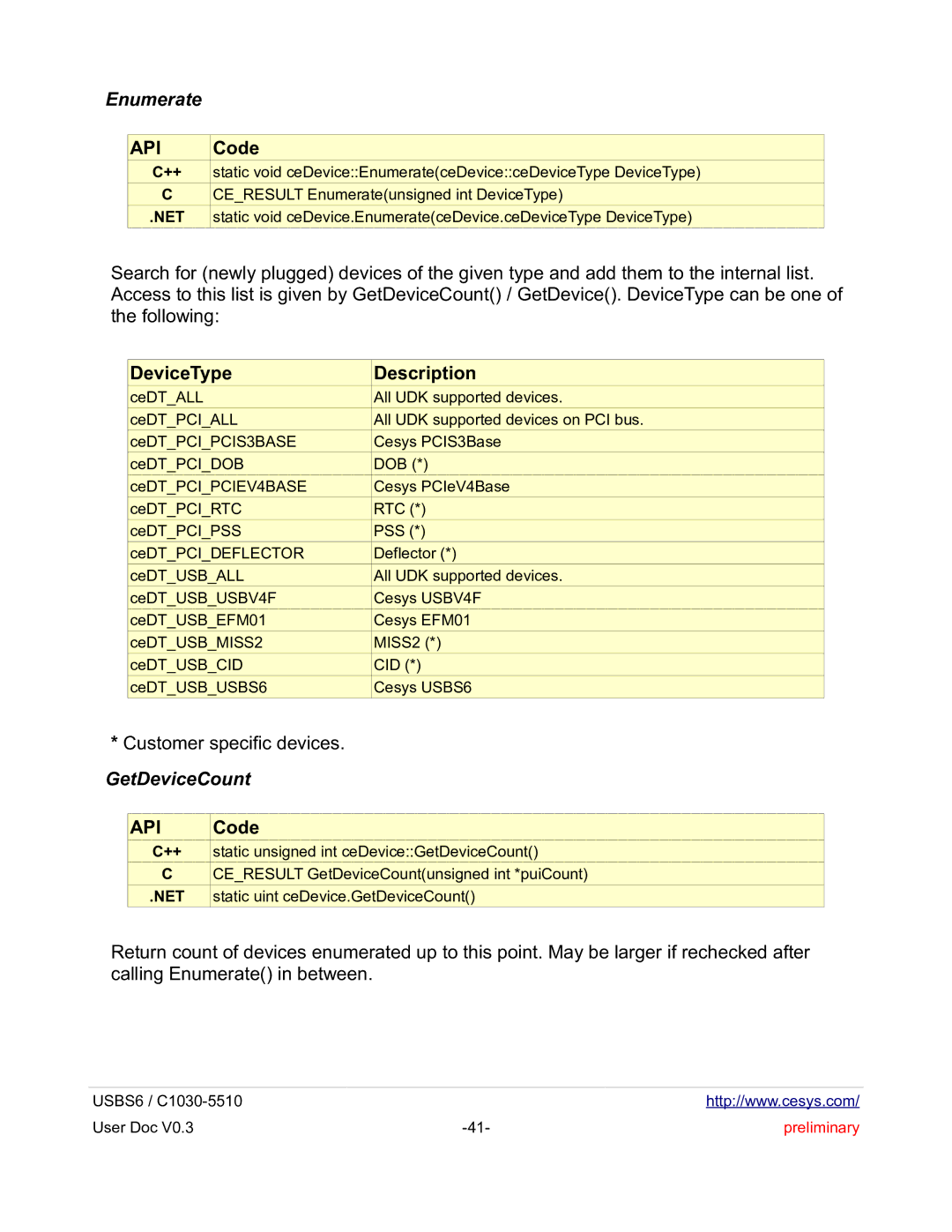
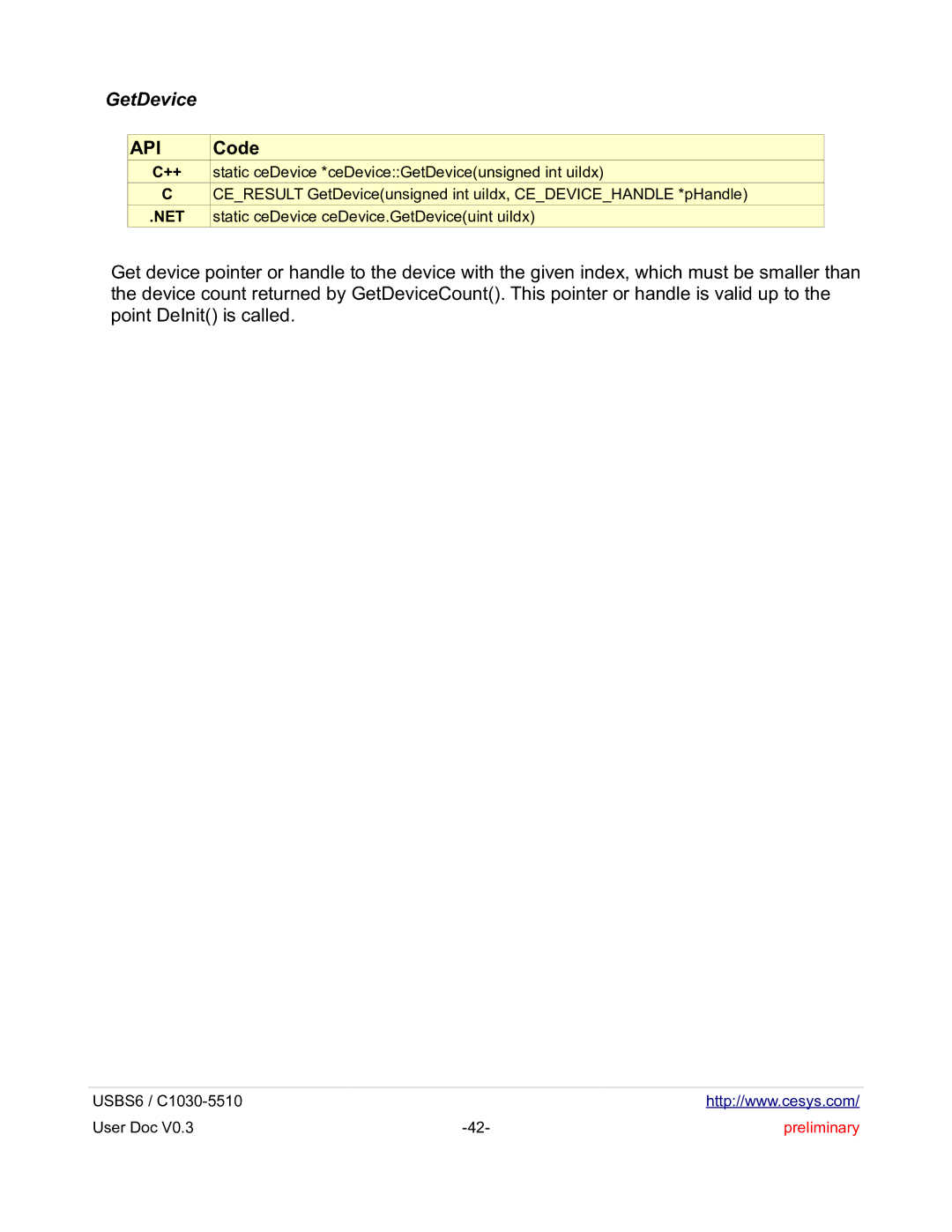
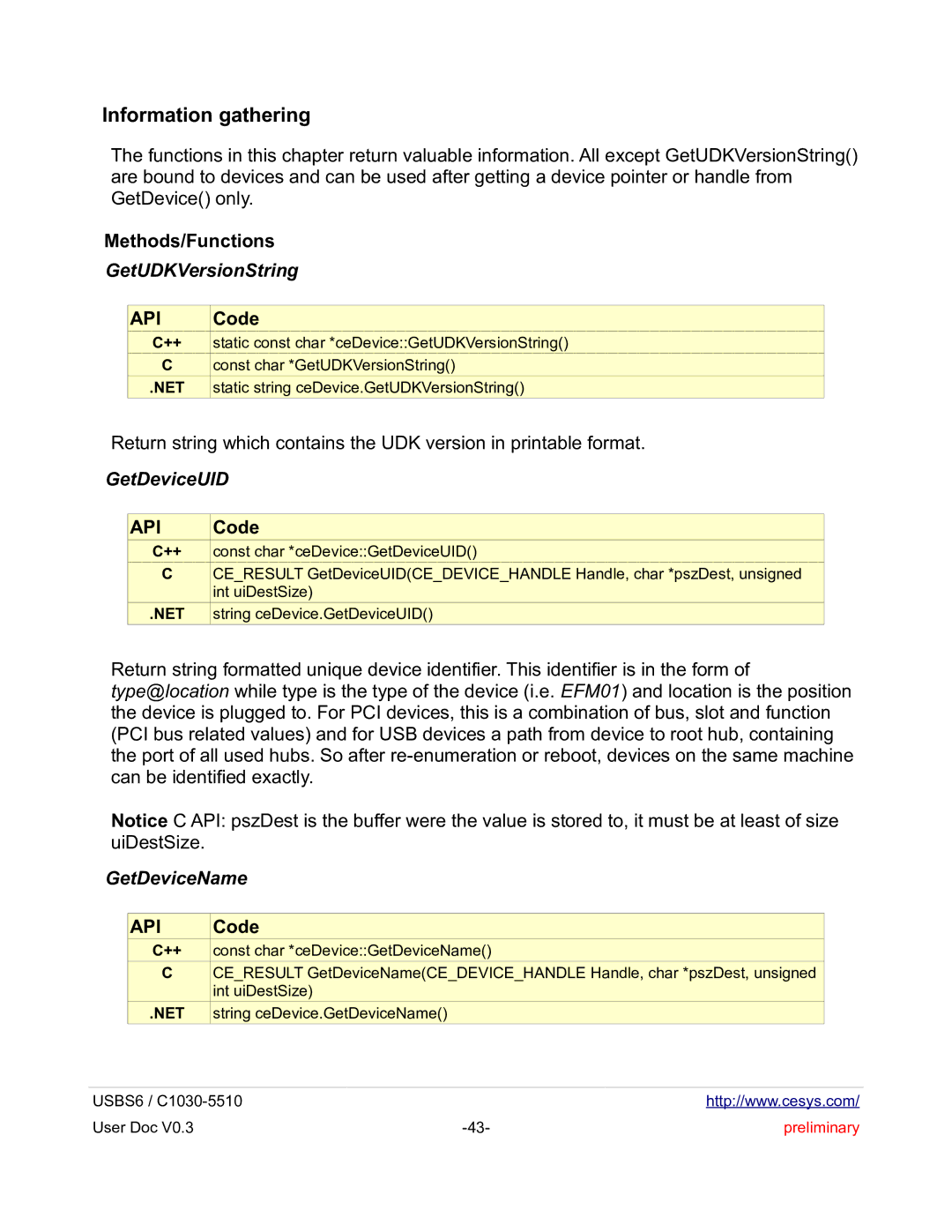
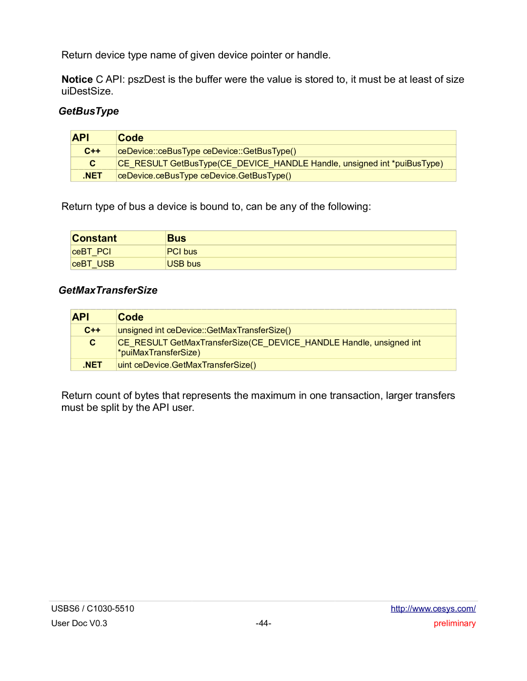
The UDK (Unified Development Kit) is used to allow developers to communicate with Cesys's USB and PCI(e) devices. Older releases were just a release of USB and PCI drivers plus API combined with some shared code components. The latest UDK combines all components into one single C++ project and offers interfaces to C++, C and for .NET (Windows only). The API has functions to mask-able enumeration, unique device identification (runtime), FPGA programming and 32bit bus based data communication. PCI devices have additional support for interrupts.

Changes to previous versions

Beginning with release 2.0, the UDK API is a truly combined interface to Cesys's USB and PCI devices. The class interface from the former USBUni and PCIBase API's was saved at a large extend, so porting applications from previous UDK releases can be done without much work.

Here are some notes about additional changes:

Complete rewrite

Build system cleanup, all UDK parts (except .NET) are now part of one large project

64 bit operating system support

UDK tools combined into one application (UDKLab)

Updated to latest PLX SDK (6.31)

Identical C, C++ and .NET API interface (.NET Windows only)

Different versions of components collapsed to one UDK version

Windows only:

Microsoft Windows Vista / Seven(7) support (PCI drivers are not released for Seven at the moment)

Driver installation / update is done by an installer now

Switched to Microsoft's generic USB driver (WinUSB)

Support moved to Visual Studio 2005, 2008 and 2010(experimental), older Visual Studio versions are not supported anymore

Linux only:

Revisited USB driver, tested on latest Ubuntu distributions (32/64)

Simpler USB driver installation

USBS6 / C1030-5510


http://www.cesys.com/

User Doc V0.3

-30-

preliminary

Image 30
Contents USBS6 June 29Copyright information Feature list Summary of USBS6Included in delivery Block Diagram XC6SLX16-2CSG324C Fpga featuresSpartan-6TMFPGA USBS6 Top View Modes of operation Powering USBS6Bus- powered USB is used as power supply input 3V@ ??? mA ModeConfiguration Jtag connectorName Signal Name USB2.0 controllerUSB2.0 FX2LPTM Microcontroller Cypresstm CY7C68013A External memory Lpddr Sdram MT46H64M16LFCK-5MCB1DQ0 Peripherals SPI Flash MX25L12845EMI-10GHEX rotary DIP switch LEDsFpga Pin N8 Fpga Pin M11 Fpga Pin M10 Fpga Pin N9 External expansion connectors USB to serial Uart interfaceDirection Comment J3 VG 96-pin external expansion connector IDC 2x25-Pin external expansion connector J4 J4 IDC 2x25-Pin external expansion connectorADDIO16 Cypress FX-2 LP and USB basics Clocking Fpga designsFX-2/FPGA slave Fifo connection Introduction to example Fpga designsISE Generate Programming File Properties Gen. Opt Disclaimer of warranty Fpga source code copyright informationFpga source code license Design usbs6soc Files and modulesSrc/wishbonepkg.vhd Src/wbmafx2.vhd Src/usbs6soctop.vhdSrc/wbintercon.vhd Src/wbslbram.vhdSrc/xiluartmacro Src/wbslmcb.vhdSrc/wbsluart.vhd Src/xilmcbmigSignals appusbh2ppktcounto70 and appusbp2hpktcounto70 Wishbone transactions Wishbone signals driven by the master Wishbone signals driven by slavesDesign usbs6bram ExampleUsbs6bram.xise Src/usbs6bramtop.vhdSrc/simtb/wbslbramtb.vhd Usbs6bram.ucfWbslbramtb.cmd Introduction Changes to previous versionsRequirements Driver installationWindows Build UDKLets assume to use c\\udkapi Linux DriversPCI Makefile creation and build Preliminary Use APIs in own projects Add project to UDK buildAPI Error handling API Functions in detail++ and .NET API GetLastErrorText GetLastErrorCodeError code Kind of error Methods/FunctionsDevice enumeration InitDeInit GetDeviceCount EnumerateDeviceType Description Static unsigned int ceDeviceGetDeviceCountGetDevice Static ceDevice *ceDeviceGetDeviceunsigned int uiIdxGetDeviceUID Information gatheringGetUDKVersionString GetDeviceNameGetBusType Constant BusGetMaxTransferSize Close Using devicesOpen Void ceDeviceOpenReadBlock ReadRegisterWriteRegister WriteBlockEnableInterrupt ResetFPGAWaitForInterrupt ProgramFPGAFromMemory SetTimeOutProgramFPGAFromBIN ProgramFPGAFromMemoryZEnableBurst Void ceDeviceEnableBurstbool bEnableUDKLab IntroductionMain screen UDKLab Main ScreenUsing UDKLab Device selection flowFpga configuration Prepare to work with deviceFpga design flashing ProjectsSequence contents Add new initializing task Content panel Sequence startRegister entry Register panelData area entry Data area panelUsing SPI-Flash for configuration How to store configuration data in SPI-FlashM25P16 Fpga Connection Jtag Signal Name Net name IO pairing and etch length reportJ3 VG-96 pin connector Differential pairs 28 IN, 12 IN/OUT Direction52.506 Etch Length mm B18 J4 IDC-50 pin connector Differential pairs 17 IN/OUT Direction Fpga Bank Etch Length mm A28Addio 42.990 Mechanical dimensions USBS6 mechanical dimensions in mmTable of contents Table of Contents USB PCI ++ API