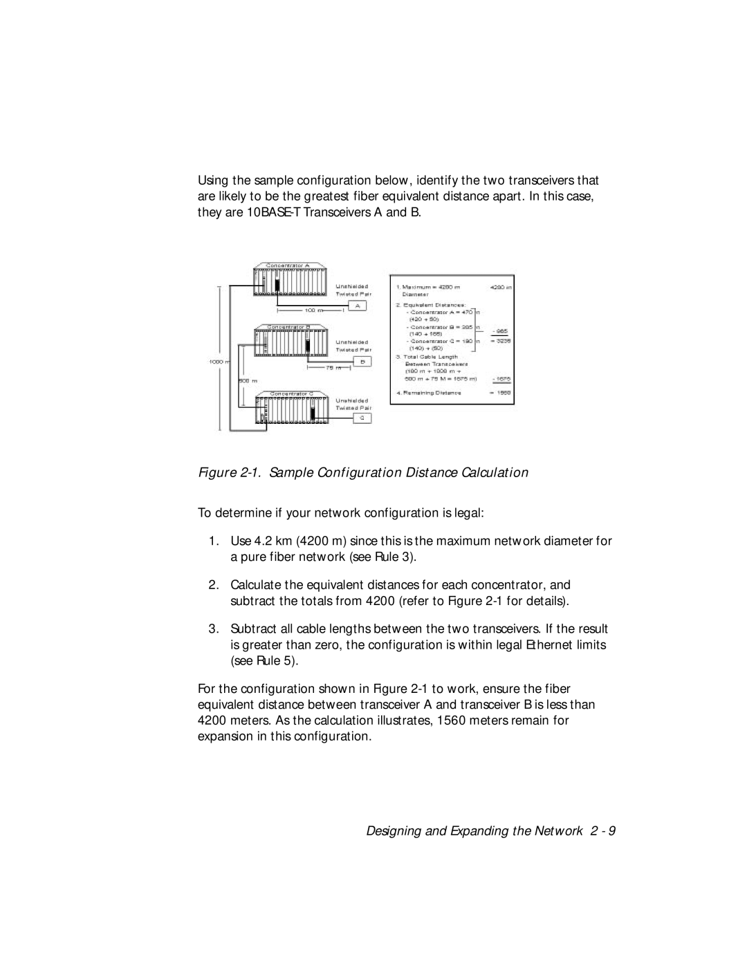
Using the sample configuration below, identify the two transceivers that are likely to be the greatest fiber equivalent distance apart. In this case, they are
Figure 2-1. Sample Configuration Distance Calculation
To determine if your network configuration is legal:
1.Use 4.2 km (4200 m) since this is the maximum network diameter for a pure fiber network (see Rule 3).
2.Calculate the equivalent distances for each concentrator, and subtract the totals from 4200 (refer to Figure
3.Subtract all cable lengths between the two transceivers. If the result is greater than zero, the configuration is within legal Ethernet limits (see Rule 5).
For the configuration shown in Figure
Designing and Expanding the Network 2 - 9