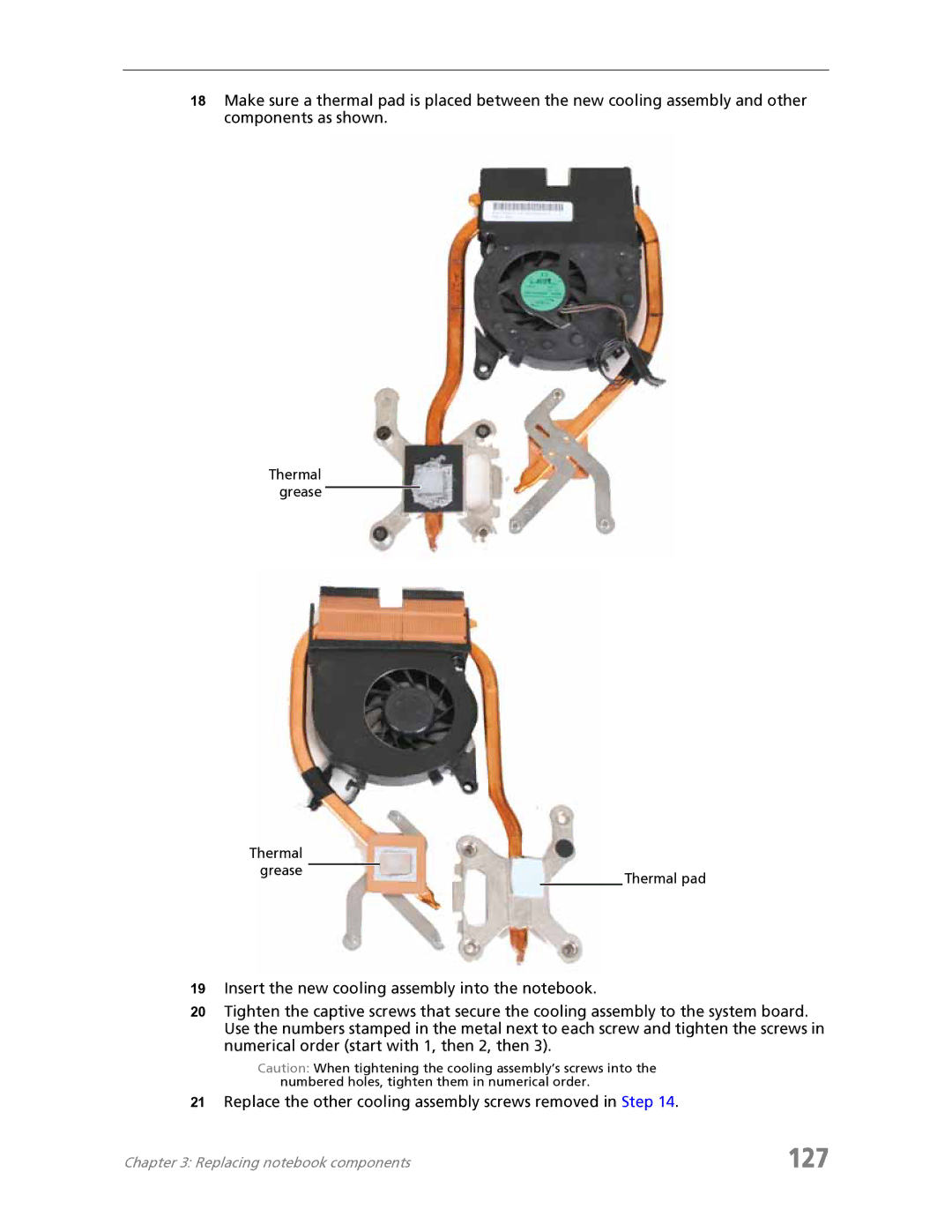
18Make sure a thermal pad is placed between the new cooling assembly and other components as shown.
Thermal grease
Thermal |
|
grease | Thermal pad |
|
19Insert the new cooling assembly into the notebook.
20Tighten the captive screws that secure the cooling assembly to the system board. Use the numbers stamped in the metal next to each screw and tighten the screws in numerical order (start with 1, then 2, then 3).
Caution: When tightening the cooling assembly’s screws into the numbered holes, tighten them in numerical order.
21Replace the other cooling assembly screws removed in Step 14.
Chapter 3: Replacing notebook components | 127 |