Chapter 6. Configuration
3=CONFIG
1=Netw. options
2=DTE options
3=Protocol
4=Quick setup
5=Security
6=Remote Config
1=Asynchronous
2=Synchronous
1=Bit Rate
2=Connector Type
3=RTS Options
4=CTS Options
5=CD Options
6=DTR Options
7=DSR Options
8=Flow Control
9=Data Format
1=Hardware Flow
2=Software Flow
3=No Flow Ctrl
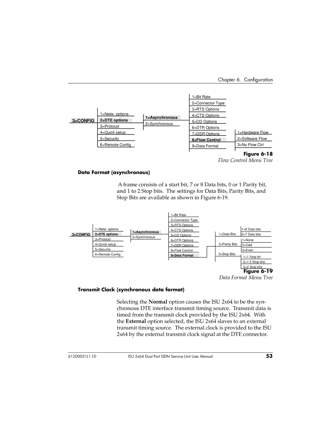
Figure
Flow Control Menu Tree
Data Format (asynchronous)
A frame consists of a start bit, 7 or 8 Data bits, 0 or 1 Parity bit, and 1 to 2 Stop bits. The settings for Data Bits, Parity Bits, and Stop Bits are available as shown in Figure
3=CONFIG
1=Netw. options
2=DTE options
3=Protocol
4=Quick setup
5=Security
6=Remote Config
1=Asynchronous
2=Synchronous
1=Bit Rate
2=Connector Type
3=RTS Options
4=CTS Options
5=CD Options
6=DTR Options
7=DSR Options
8=Flow Control
9=Data Format
|
| 1=8 Data bits |
| |
1=Data Bits |
| 2=7 Data bits |
| |
2=Parity Bits |
| 1=None |
| |
| ||||
| 2=Odd |
| ||
|
| |||
|
| 3=Even |
| |
3=Stop Bits |
| 1=1 Stop bit |
| |
|
| |||
|
| 2=1.5 Stop bits |
| |
|
| 3=2 Stop bits | ||
|
| Figure |
| |
Data Format Menu Tree
Transmit Clock (synchronous data format)
Selecting the Normal option causes the ISU 2x64 to be the syn- chronous DTE interface transmit timing source. Transmit data is timed from the transmit clock provided by the ISU 2x64. With the External option selected, the ISU 2x64 slaves to an external transmit timing source. The external clock is provided to the ISU 2x64 by the external transmit clock signal at the DTE connector.
ISU 2x64 Dual Port ISDN Service Unit User Manual | 53 |