Table
Printed Circuit | Block Name | Ref. | Perform These Procedures |
Board |
| Desig. |
|
|
|
|
|
A8 GPIB Board | Voltage DAC | All | Remote Readback Zero Calibration |
|
|
| Constant Voltage Full Scale Calibration |
|
|
| Voltage Monitor and Remote Readback Full |
|
|
| Scale Calibration |
|
|
| Constant Voltage Zero Calibration |
|
|
|
|
A8 GPIB Board | Current DAC | All | Constant Current Zero Calibration |
|
|
| Constant Current Full Scale Calibration |
|
|
|
|
A8 GPIB Board |
| U5 | Remote Readback Zero Calibration |
|
|
| Constant Voltage Full Scale Calibration |
|
|
| Voltage Monitor and Remote Readback Full |
|
|
| Scale Calibration |
|
|
| Constant Voltage Zero Calibration |
|
|
| Constant Current Full Scale Calibration |
Initial Setup
a.Unplug the line cable.
b.Remove the top cover by removing the two
c.Plug a control board test connector onto the A2J7 card edge fingers.
d.Turn OVERVOLTAGE ADJUST control A3R72 fully clockwise.
e.Disconnect all loads from output terminals.
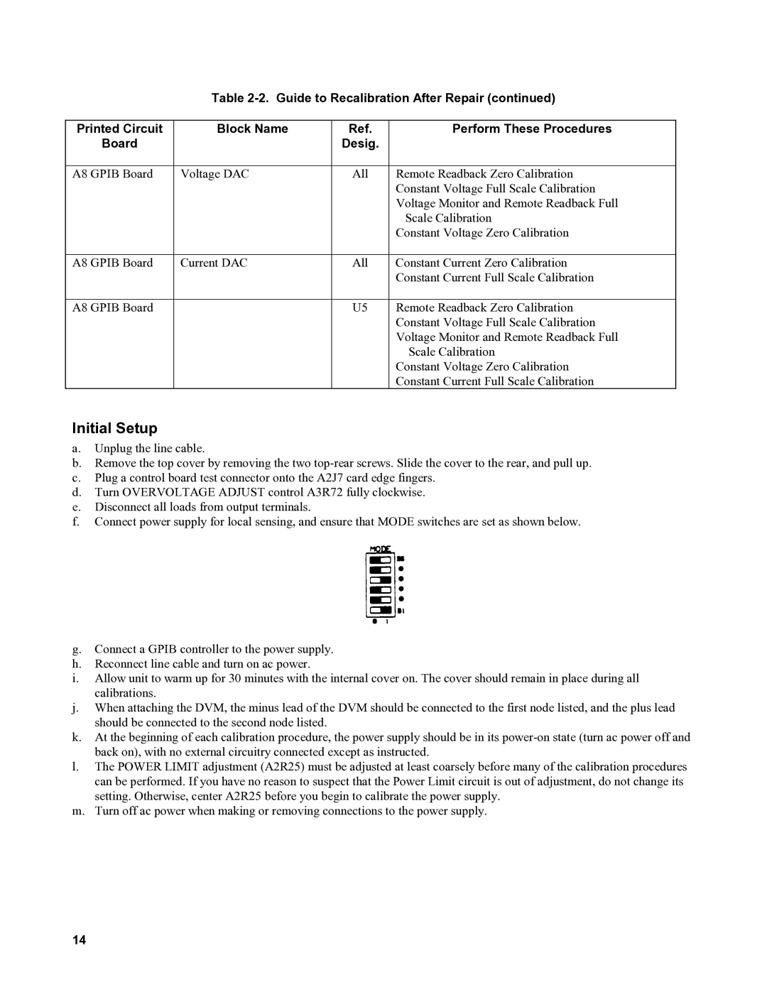
f.Connect power supply for local sensing, and ensure that MODE switches are set as shown below.
g.Connect a GPIB controller to the power supply.
h.Reconnect line cable and turn on ac power.
i.Allow unit to warm up for 30 minutes with the internal cover on. The cover should remain in place during all calibrations.
j.When attaching the DVM, the minus lead of the DVM should be connected to the first node listed, and the plus lead should be connected to the second node listed.
k.At the beginning of each calibration procedure, the power supply should be in its
l.The POWER LIMIT adjustment (A2R25) must be adjusted at least coarsely before many of the calibration procedures can be performed. If you have no reason to suspect that the Power Limit circuit is out of adjustment, do not change its setting. Otherwise, center A2R25 before you begin to calibrate the power supply.
m.Turn off ac power when making or removing connections to the power supply.
14