Setup. The Main Troubleshooting Setup, Page 53, except connect the external supply to the unit's + OUT ( + ) and - OUT
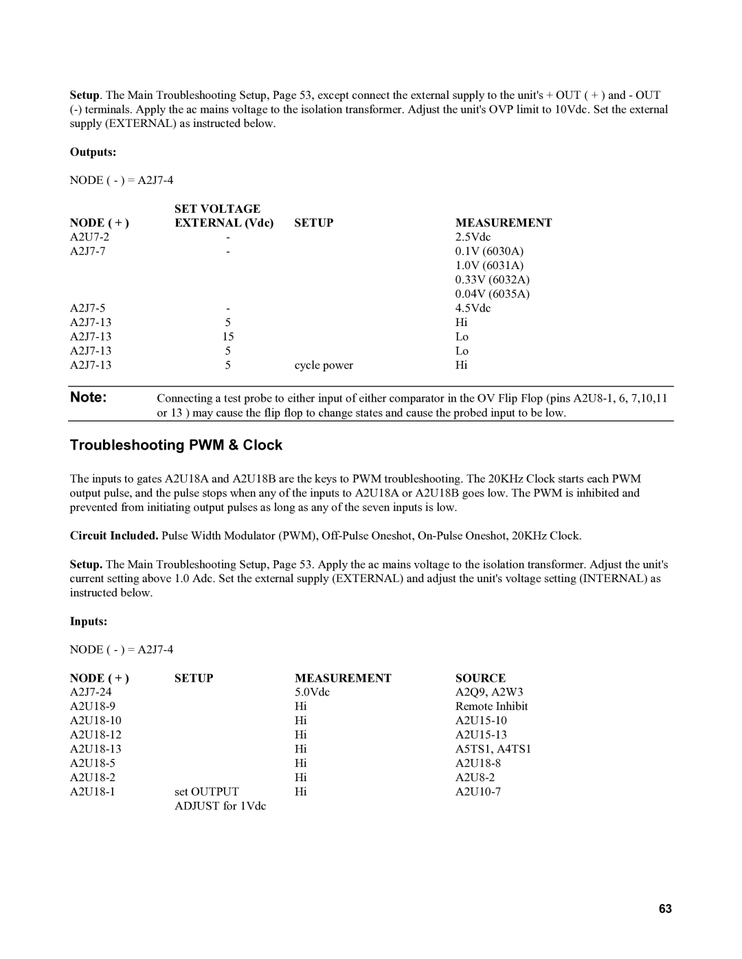
Outputs:
NODE ( - ) =
| SET VOLTAGE |
|
|
NODE ( + ) | EXTERNAL (Vdc) | SETUP | MEASUREMENT |
- |
| 2.5Vdc | |
- |
| 0.1V (6030A) | |
|
|
| 1.0V (6031A) |
|
|
| 0.33V (6032A) |
|
|
| 0.04V (6035A) |
- |
| 4.5Vdc | |
5 |
| Hi | |
15 |
| Lo | |
5 |
| Lo | |
5 | cycle power | Hi |
Note: Connecting a test probe to either input of either comparator in the OV Flip Flop (pins
Troubleshooting PWM & Clock
The inputs to gates A2U18A and A2U18B are the keys to PWM troubleshooting. The 20KHz Clock starts each PWM output pulse, and the pulse stops when any of the inputs to A2U18A or A2U18B goes low. The PWM is inhibited and prevented from initiating output pulses as long as any of the seven inputs is low.
Circuit Included. Pulse Width Modulator (PWM),
Setup. The Main Troubleshooting Setup, Page 53. Apply the ac mains voltage to the isolation transformer. Adjust the unit's current setting above 1.0 Adc. Set the external supply (EXTERNAL) and adjust the unit's voltage setting (INTERNAL) as instructed below.
Inputs:
NODE ( - ) =
NODE ( + ) | SETUP | MEASUREMENT | SOURCE |
| 5.0Vdc | A2Q9, A2W3 | |
| Hi | Remote Inhibit | |
| Hi | ||
| Hi | ||
| Hi | A5TS1, A4TS1 | |
| Hi | ||
| Hi | ||
set OUTPUT | Hi | ||
| ADJUST for 1Vdc |
|
|
63