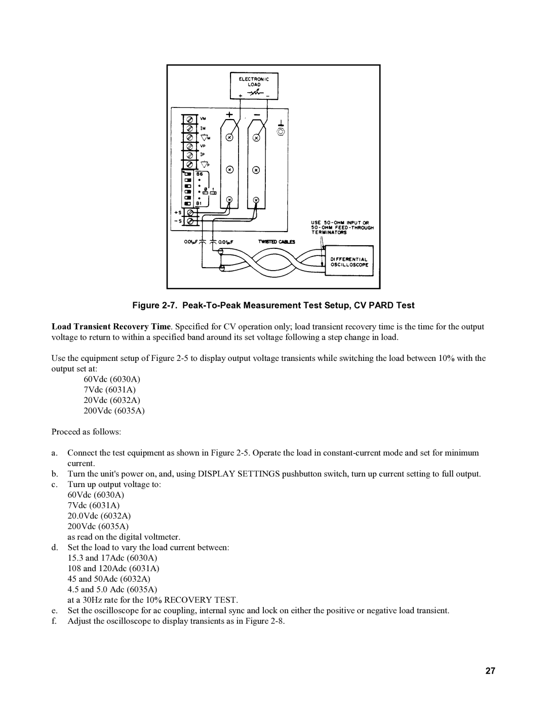
Figure 2-7. Peak-To-Peak Measurement Test Setup, CV PARD Test
Load Transient Recovery Time. Specified for CV operation only; load transient recovery time is the time for the output voltage to return to within a specified band around its set voltage following a step change in load.
Use the equipment setup of Figure
60Vdc (6030A) 7Vdc (6031A) 20Vdc (6032A) 200Vdc (6035A)
Proceed as follows:
a.Connect the test equipment as shown in Figure
b.Turn the unit's power on, and, using DISPLAY SETTINGS pushbutton switch, turn up current setting to full output.
c.Turn up output voltage to: 60Vdc (6030A)
7Vdc (6031A) 20.0Vdc (6032A) 200Vdc (6035A)
as read on the digital voltmeter.
d.Set the load to vary the load current between:
15.3and 17Adc (6030A)
108 and 120Adc (6031A)
45 and 50Adc (6032A)
4.5and 5.0 Adc (6035A)
at a 30Hz rate for the 10% RECOVERY TEST.
e.Set the oscilloscope for ac coupling, internal sync and lock on either the positive or negative load transient.
f.Adjust the oscilloscope to display transients as in Figure
27