i.Adjust A2R26 (UPPER KNEE) clockwise until front panel CV LED turns on. Power supply output should be: 200 ±0.4V @5.25A in CV mode (6030A)
20.5±0.5V @55A in CV mode (6031A) 60 ±0.4V @18.2A in CV mode (6032A) 500 ±0.4V @2.2A in CV mode (6035A)
Resistance Programming Full Scale Calibration
a.Send string ''OUT OFF".
b.Connect a 2K ohm calibration resistor from ![]() P to VP on rear panel.
P to VP on rear panel.
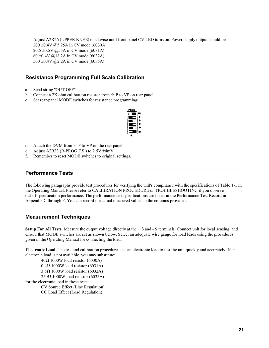
c.Set
d.Attach the DVM from ![]() P to VP on the rear panel.
P to VP on the rear panel.
e.Adjust A2R23
f.Remember to reset MODE switches to original settings.
Performance Tests
The following paragraphs provide test procedures for verifying the unit's compliance with the specifications of Table
Measurement Techniques
Setup For All Tests. Measure the output voltage directly at the + S and - S terminals. Connect unit for local sensing, and ensure that MODE switches are set as shown below. Select an adequate wire gauge for load leads using the procedures given in the Operating Manual for connecting the load.
Electronic Load. The test and calibration procedures use an electronic load to test the unit quickly and accurately. If an electronic load is not available, you may substitute:
40Ω 1000W load resistor (6030A)
0.4Ω 1000W load resistor (6031A)
3.5Ω 1000W load resistor (6032A)
250Ω 1000W load resistor (6035A) for the electronic load in these tests:
CV Source Effect (Line Regulation)
CC Load Effect (Load Regulation)
21